
jdowning - 3-27-2008 at 05:22 PM
"Half Binding" - is an edge treatment of a soundboard where a decorative inlay or binding (or banding) is glued into a narrow ledge or rebate cut to
half the depth of the soundboard. The half binding - like a full depth binding - reinforces the edge of the soundboard against damage but also
introduces a controlled weakness around the edge of the soundboard that may affect soundboard response.
Half binding can be found on some ouds as well as on some lutes of the 16th and 17th C.
As I will soon have a need to cut a half binding on a lute currently under construction (and plan to apply this technique at a later date to the
construction of an oud), I decided to go ahead and prepare some basic tools in advance to do the job by hand. Cutting a rebate for a half banding is a
fairly delicate procedure due to the thinness of a typical oud or lute soundboard - the depth of rebate being only about 0.8 to 1.0 mm. It can be done
with a small electric router or by hand with a purfling cutter and a chisel to cut the ledge - a lot slower but quieter and easier on the nerves.
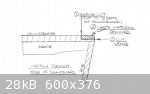
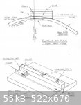
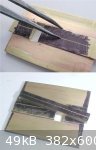
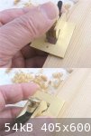
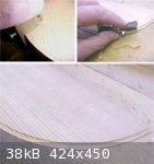
The attached image shows the process involved. A scoring cut to half the depth of the soundboard is first made around the full circumference of the
soundboard. The ledge is then cut level to remove the waste.
In "Historical Lute Construction" (Guild of American Luthiers), the late Robert Lundberg uses a tool that he adapted from a small, brass, instrument
maker's plane to facilitate accurate cutting of the rebate ledge. Inspired by this - but not having a spare (and costly) instrument maker's plane
lying around that could be used, I have decided to see what might be done instead by modifying a readily available and low cost miniature woodworking
plane. No guarantee that it is going to work out but worth a try.
SamirCanada - 3-27-2008 at 07:53 PM
Looking forward to this thread John.
its going to be extremely useful for me as well.
Jameel - 3-28-2008 at 04:56 AM
I'll be watching this one.
jdowning - 3-28-2008 at 12:39 PM
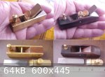
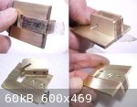
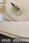
There are likely a number of different styles of miniplane on the market. Two are shown in the attached images - essentially of similar design. The
first with a body of rosewood with brass side plates is sold by Busy Bee Tools, Canada, in a kit of 7 mini woodworking tools (The boxed kit, Model
B2675, is currently on sale at $46 plus shipping which works out at less than $8 per tool). The second, with a body of ebony, is sold by Lee Valley
Tools of Ottawa (Cat# 07P15.01 at $17 plus shipping). The latter - although more expensive (!) - is of much better quality and nicely finished. Both
planes have 1/2 inch wide blades.
The ebony plane is so well made and finished that I do not plan to modify it for this project - although it could be used. It will otherwise be very
handy for delicate trimming work.
The brass plane is less well made and finished and requires some work to adjust the blade setting etc. but it should be just fine as a starting point
for the project.
jdowning - 3-29-2008 at 07:27 AM
As this is a design project in progress, another alternative to the mini block plane conversion currently under consideration is to modify a mini
chisel plane.
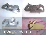
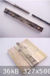
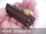
The objective of the exercise is to make a tiny rebate (or rabbet) plane. For comparison, the attached images show two full sized cabinet maker's
rabbet planes - a Stanley #90 'bull nose' and a Stanley #78. The Stanley #90 is a basic plane with no guides or 'fences' to set the depth or width of
a rebate - it is used freehand. either right or left handed as the blade width is the same as the width of the body of the plane. The bull nose
feature allows the plane to be worked close to a blind corner. The cap of this plane may also be removed to convert it to a chisel plane. The Stanley
#78 has a number of adjustments and features including a depth stop, a fence, a conventional as well as a bull nose blade configuration and can also
be used left or right handed. This plane also has a 'built in' scoring cutter (below the depth stop) to facilitate cross grain planing.
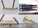
The mini chisel plane is from the Busy Bee miniature woodworking kit. Alternatively Lee Valley sell a miniature chisel plane with ebony body (Cat#
07P15.05, $16.95) which could also be used (this plane and matching block plane (mentioned in the previous post) can also be purchased as a pair for
$29.50 plus shipping - Cat# 07P15.10).
Modifying a mini chisel plane (by adding a cap, depth stop and fence) would have the advantage of creating a more compact plane than a mini block
plane conversion and allow the plane to be worked closer to a neck joint on an instrument. Also, if fitted with a fixed central guide, the plane could
be used either left or right handed - to avoid cutting 'against the grain' in use. Although few details of the tool are given in his book, the tiny
rebate plane used by Robert Lundberg can only be used in one direction - so the blade must have a very fine set to avoid wood grain 'tear out'.
However, as the Lundberg plane used this way obviously does work, either alternative should be viable.
jdowning - 3-30-2008 at 12:33 PM
I have decided to go ahead with modifying the chisel plane.
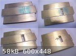
The body of the plane has been shortened by cutting it just behind the blade position and the blade retainer has also been shortened to remove
unnecessary surplus material. The clamping screw will also be shortened to lower the overall profile of the plane. There is sufficient material
remaining from which to make another plane.
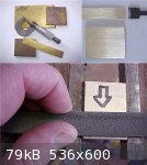
The next step will be to remove about 3 mm from the base (the cross hatched area) and to make the base and sides of the body "square" to each other.
This will be done by hand filing. The intention is to then mount the body on to a brass baseplate fitted with a central guide underneath to allow the
completed plane to be used either left and right handed. The baseplate will be made wider than the plane body to provide support on the soundboard. A
slot cut in the baseplate will allow the blade to project through.
Checking data that I have on file, the width of the half banding found on surviving lutes of the 16/17th C varies between
1.5 mm and 4.5 mm - the most common width being between 2mm and 3mm. I do not have equivalent data for ouds but figure that the average banding width
for an oud might be around 5mm?
As the width of the plane body is just under 13 mm, the central guide for the plane would need to range between 10mm wide to 3 mm wide to cover the
above banding width range. The guide width might be fixed or the plane designed to accommodate guides of different thicknesses. So a lute maker might
require a plane with a 7 mm thick guide which would result in a rebate 3mm wide and an oud maker might require a plane with a 3mm thick guide which
would give a 5 mm wide rebate.
Jameel - 3-30-2008 at 01:51 PM
Lundberg's has a toe, do you think it will work without? Nice progress so far.
jdowning - 3-30-2008 at 06:01 PM
The modified chisel plane cannot be used 'as is' (the blade would just 'dig in' if it was) but is to be mounted upon a baseplate with the blade
passing through a slot in the plate. The front section of the plate will form the 'toe', set close to the cutting edge of the blade in order to
control the cutting action required to produce a fine shaving and minimise the risk of grain tear out.
The Lundberg plane - as far as I can determine from the images in the book - has a large gap between the cutting edge and toe - so the toe in this
case - while helping to keep the tool level, would otherwise seem to have minimal influence on efficient cutting action. But perhaps it does not
matter too much if extremely fine cuts and multiple passes are made (Lundberg says that a complete rebate takes about twenty passes of the plane to
complete).
jdowning - 3-31-2008 at 07:49 AM
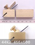
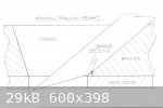
The attached sketches may help to clarify what I am trying to achieve.
The first sketch is a plan view of the plane - drawn to scale - as it would be when used 'right handed'. The soundboard curve is the profile of a new
lute currently under construction (which also matches the profile of my oud). Both lute and oud happen to have a 4 mm wide edge banding so the plane
will be constructed to cut that width of rebate. The plane will be mounted on a baseplate screwed to the underside of the plane so that the baseplate
may be replaced if required. The baseplate will measure about 40 mm by 20 mm and will be fabricated from brass sheet with the components - soft
soldered together after shaping - so that it may be easily made with hand tools. Alternatively the baseplate could be machined from a single piece of
brass using a milling machine.
The isometric sketch represents the underside of the baseplate - shown without the corners and sharp edges rounded off (as they will be on the
finished plane). The throat is a rectangular slot cut through the plate, just wide enough to accommodate the blade (to eliminate any sideways movement
in use). The depth of the rebate will be controlled by means of a strip of brass of the required depth (in this case about 0.8 mm) made to the same
width as the throat and soldered to the baseplate. A guide of the required width and exactly centered is then soldered to the depth gauge and the
entire assembly screwed to the underside of the plane.
To cut a narrower rebate than 4 mm, the width of the throat, depth gauge and blade would have to be adjusted accordingly - the blade being ground away
on both sides to fit the throat width.
jdowning - 3-31-2008 at 12:39 PM
I should add that the obvious alternative to making replaceable baseplates (to provide for various banding widths) is to make a series of planes each
dedicated to a specific rebate width. This, however, would likely only be a requirement for a professional lute maker making a range of copies of
historical instruments.
In my case, I would need only two planes - the one currently being developed in this thread - producing a rebate width of about 4 mm, good for ouds as
well as for the liuto attiorbato in " Old Project - New Lute" - and another for a rebate width of about 2.5 mm which would adequately cover most late
16th C and 17th C lutes.
A second plane can be made from the remainder of the body of the original chisel plane and a blade cut from a scraper blade or spokeshave blade and
ground to the required profile. Two for the price of one (with a bit of extra work)!
Note also - that as the design progresses and develops - the central guide, previously stated to be of variable width - is now to be of fixed width -
regardless of the rebate size - in order to keep the overall width of the baseplate to a minimum. Also, the baseplate design now includes a depth
guide to limit the depth of the rebate so that the blade can be set for a fine cut at the outset and the plane will cut only to the required depth
without further blade adjustments. For a 1.5 mm spruce or pine soundboard this depth can be fixed at about 0.8 mm or about 1mm for a thicker
soundboard of cedar, say.
SamirCanada - 3-31-2008 at 04:20 PM
wow thanks a lot john.
Maybe I can come by sometime after April 20th(last exam day) since I will be graduated and I will have somewhat more free time for things like
this.
Let me know when I can come by.
jdowning - 4-1-2008 at 12:27 PM
Hi Samir - looking forward to your visit but it will have to be delayed to around the end of May at the earliest as I have quite a full schedule until
then. (Also this place is about to become a bit of a mud bath for a while as the metre or so of snow, that we have on the ground, thaws out - oh the
joys of country living!).
I will telephone you around the end of May to fix a time and date. Bring your oud!
Good luck with your Final exams.
John
jdowning - 4-1-2008 at 03:15 PM
Before starting to cut metal and make the baseplate, the dimensions of the throat need to be established.
The baseplate will be made from a piece of sheet brass 1/8 inch thick and the depth gauge made from sheet brass 0.035 inch thick.
Making a scale drawing of a section through the throat of the plane - the blade being 0.057 inch thick set at 40 degrees, and allowing for a very fine
set of the blade - gives a minimum opening of the throat of about 0.14 inch. Actually this dimension is not absolutely critical as future adjustments
can be made either by shimming the blade, using a thicker blade or by filing the front edge of the throat, to obtain the optimum setting - but it is a
starting point.
jdowning - 4-2-2008 at 12:55 PM
The blanks for the baseplate and depth gauge are cut from sheet brass. Both are cut well oversize so that assembly is non critical and to allow the
baseplate to be shaped exactly to final dimensions - dimensions determined after assembly and testing of the plane.
The baseplate blank is about 35mm by 45mm and 3mm thick and the depth gauge blank is just over 13mm wide by about 50mm long and 0.94mm thick. The
thickness of the depth gauge will be reduced to about 0.8mm after assembly of the baseplate.
As the sheet brass has surface scratches and is not completely flat, the baseplate blank was prepared first by filing the surfaces and then by rubbing
the blank on emery cloth placed on a hard, flat surface. The depth gauge blank was prepared only by dressing on emery cloth to remove scratches and
surface corrosion.
To create a flat surface for the baseplate, "draw" filing was used - a technique where a flat file is laid on the work surface and is drawn (or
pushed) with both hands holding the file on either side of the work providing equal pressure.
Flatness of the surface is tested by placing a straight edge on the surface and holding the work up to the light to reveal any surface irregularities.
This is a pretty severe test but ensures good accuracy.
jdowning - 4-2-2008 at 02:00 PM
The first step in making the baseplate is to solder the depth gauge to the plate. Precise alignment of the depth gauge to the sides of baseplate is
not required as the depth gauge has been filed parallel to a width just under the width of the plane blade and will be the reference surface for
squaring up the baseplate later.
Lead free soft solder (available from any hardware store) was used as it had a higher melting point than a 50/50 lead/tin alloy solder.
After checking that the depth gauge is flat and a close fit to the baseplate, the mating surface is tinned with solder. To do this the mating surfaces
are cleaned of any residual dirt or grease with alcohol. The depth gauge mating surface is then coated with a thin layer of solder by first coating
the surface with acid paste flux and then melting solder over the entire surface by heating with a soldering iron or propane torch - spreading the
melted solder evenly, while still molten, with a small brush dipped in flux. The base plate is then coated with flux and the depth gauge clamped in
position with a couple of metal spring clamps. The entire assembly is then heated with a propane torch until solder is seen to flow evenly along the
edges of the depth gauge. This method of soldering ensures that the entire mating joint surfaces are coated with the minimum of excess solder. Too
much solder is to be avoided.
The assembly is then cleaned of flux by washing in hot soapy water and dressed again with a file and emery cloth to ensure flatness. Any surplus soft
solder may be cleaned up with a small cabinet scraper.
jdowning - 4-3-2008 at 12:25 PM
With the depth gauge soldered in place and the baseplate cleaned up, work has started on cutting the throat.
The edge of the depth gauge is now the reference for the layout. The throat position was coated with engineer's marking ink and the outline of the
throat marked with a scriber (marking ink is not essential, it just helps to show the scribed lines better).
The throat area was then 'chain drilled' with a line of three 1/8 inch diameter holes and the spaces between cut through with a needle file. For
delicate work, in metal or wood, needle files are very useful and readily available Chinese files - good enough for most work - are cheap to buy (for
example, a pack of ten assorted files currently on sale costs $2.00 from Busy Bee). Needle files were then used to open the slot almost to the
finished dimensions.
The trailing edge of the slot - on the upper surface of the baseplate, where the plane is to be mounted - must be filed to an angle of 40 degrees to
match the blade angle, providing support for the cutting edge of the blade.
(Note that I have not taken the trouble to correct the close up images for 'barrel' distortion - so lines that seem to be curved are, in fact,
straight)
jdowning - 4-3-2008 at 12:50 PM
The body of the plane has been reduced in height - by filing, and finished on emery cloth placed on a flat surface - to remove material amounting to
the same thickness as the baseplate - about 3mm - in order to keep the overall height of the finished tool to a minimum. The side plates were first
coated with marking ink and reference lines scribed on each side plate with compasses set to a gap of 3mm.
A problem was encountered during the filing operation. The plane body was clamped in a bench vise fitted with rubber jaws to prevent scratching of
the side plates. Unfortunately the clamping forces caused the side plates to be squeezed together at the front end of the plane - where the side
plates are unsupported by the wooden core. This distortion amounts to a total of about 0.020 inch but - as it will not affect the proper functioning
of the finished tool - will be left uncorrected. There is no evidence of the sideplates separating from the wooden core. Hopefully they are well glued
in place.
Nevertheless, in order to now provide full support to the side plates, the plan is to eventually permanently glue the plane body to the base plate
with epoxy cement.
OudandTabla - 4-3-2008 at 08:58 PM
Wow, I enjoy watching your precise work. It must be very rewarding to make your own tools. I look forward to watching this thread.
jdowning - 4-5-2008 at 12:43 PM
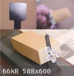
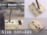
The blade that came with the plane was not accurately ground by the manufacturer so that the cutting edge was not square with the sides. The blade
needs to be square in order to be a proper fit in the throat. Squaring the blade was done on an oil stone. Due to the small size of the blade, a
simple blade holder was made from a small block of pine with a shallow slot cut in one end. The blade was made a tight fit in the slot and held in
place with push pins. After squaring the blade, the bevel was reshaped with a diamond coated needle file, after which the blade was sharpened and
honed.
At this stage, the quality of the steel of the blade is unknown but it can easily be replaced later if it proves unsatisfactory.
The blade is 1.5 mm thick but the plane can accommodate a thicker blade if necessary (such as the 2mm thick high speed steel blades that come with the
Lee Valley mini planes).
jdowning - 4-10-2008 at 12:35 PM
The first baseplate has been scrapped as I had not left sufficient room for adjustment in locating the throat. No problem - measure twice, cut
once!
The second attempt is a larger, oversize blank allowing plenty of room for trimming later.
The throat was made a bit wider (longitudinally) than originally designed - 4.7mm - so that filing of the 40 degree angle on the top side of the
baseplate was made easier. This gives adequate clearance for the needle file against the leading edge of the throat.
The depth gauge is made a fraction narrower than the blade width so that the plane will cut a rebate with sharp inside corners.
jdowning - 4-10-2008 at 12:52 PM
The guide has been cut from some 3mm thick plate, filed parallel, square and a little oversize in width to allow for final adjustment after assembly.
The centre lines have been marked out ready for drilling the mounting holes - using marking ink and compasses.
The baseplate has been trimmed to almost its finished length.
jdowning - 4-11-2008 at 12:15 PM
To mount the body of the plane to the baseplate, two pilot holes 1.5 mm in diameter were first drilled through the baseplate on the scribed centre
line.
With the plane blade in position (to correctly register the front of the plane), the centre of the back of the body was aligned with the centreline of
the baseplate. The body was then temporarily fixed in position using 'transfer tape'. Transfer tape is a thin, double sided, adhesive tape strong
enough to hold the body in correct alignment during the drilling operation. Transfer tape costs $6.75 for a 30 metre roll from Lee Valley, cat #
25U03.20.
With the body in place the pilot holes were drilled through to a diameter and depth providing proper clearance for two brass wood screws. The fit of
the screws must not be too tight to avoid splitting the plane body. The baseplate was then countersunk so that the heads of the screws are seated
below the surface of the depth gauge.
After separating the body from the baseplate the glue residues were removed with 'Glue Gone' solvent.
The body of the plane will later be fixed permanently to the base plate with epoxy cement
At this stage the baseplate is well oversize in width and will be trimmed to a more convenient size to be determined after testing the completed
tool.
jdowning - 4-13-2008 at 12:55 PM
The final part of the work is to fit the guide.
With this design of plane, the blade must be inserted from underneath the baseplate so the guide must be made so that it can be easily removed. In
view of this, the design of the tool has been revised to accommodate different widths of guide so that the rebate width can be varied by simply
changing the guide with one of a different width.
The guide is fixed to the baseplate by two, round headed, brass screws. In this case the screws I am using have a 6 BA thread - a thread standard
(British Association) that I suppose is now obsolete but any fine thread screw will do.
The guide is first drilled with two mounting holes using a drill that is the same diameter as the core of the engineer's tap that will be used to cut
the screw threads in the baseplate. The guide is then aligned on the baseplate centre line, temporarily held in position with transfer tape and used
as a jig for drilling the exact location of the screw holes in the baseplate.
jdowning - 4-13-2008 at 02:08 PM
First, the rear hole for the guide is drilled in the baseplate and the screw thread cut with a machinist's tap. It is important to keep the tap
vertical during this operation. The rear hole in the guide itself is then drilled to a close clearance diameter for the screw thread. With the guide
held in place with the rear screw, the guide is positioned central in the plane throat - using a drill shank of the required diameter as a gauge. The
front hole is then drilled through the guide into the baseplate and the hole threaded in the same manner as for the rear hole. The hole in the guide
is again drilled to a clearance diameter and the front screw fitted in place.
jdowning - 4-13-2008 at 02:30 PM
With the prototype tool in its unfinished state - and not knowing if it will work or not - some preliminary trial cuts were made in a Sitka spruce
test piece. The test piece was made about the size of a small, almond shaped, descant lute soundboard with a maximum diameter of 190 mm and length 340
mm - with grain running longitudinally and cut on the quarter.
The tool is designed to be used either left or right handed in order to cope with the varying directions of the sound board grain when cutting the
rebate. However, this does not mean that the user has to be ambidextrous because the plane can be used with one hand and either pushed or pulled to
make a cut.
jdowning - 4-13-2008 at 03:02 PM
The prototype plane has been made with a depth gauge of
0.81 mm fixed depth and a guide measuring 4.7 mm wide. This combination should give a rebate measuring 4 mm wide by 0.81 mm deep in section.
(For a rebate measuring 2.5 mm X 0.81mm, the guide would be replaced by one measuring 7.7 mm wide).
The plane worked reasonably well in producing a rebate of the intended dimension. The cross grain cuts (around the bottom diameter of a sound board) -
as expected - were the most demanding and required a scribing cut (with a purfling or binding cutter of the kinds described in other threads on this
forum) whereas the cut along the grain direction did not strictly require this pre treatment.
Shavings tended to jam in the outer corners of the throat but were regularly cleared with a wooden toothpick and small brush. Some small adjustments
to the throat of the plane might help to improve this situation.
The current baseplate dimension of about 38 mm X 40 mm does not seem to be over large in practice as it helps in maintaining better handling and
control of the tool. So, the corners and sharp edges of the baseplate will just be rounded over to make the tool more comfortable to handle.
The test results are encouraging enough for me to spent a bit more time in finishing the tool to final dimensions and making further fine adjustments
to improve cutting action.
SamirCanada - 4-13-2008 at 07:06 PM
BRAVO!!

Jameel - 4-14-2008 at 11:00 AM
Niiiiiiiiice. I'm saving this post on my hard drive. Gotta make me one! Keep us posted.
jdowning - 4-14-2008 at 12:51 PM
Thanks for your interest everyone.
I am in the process of putting the finishing touches to the prototype and also making an alternative guide that will be used to cut a narrower rebate
about 2.5 mm wide. In light of the number of design changes made as work has progressed I shall conclude the thread later with a summary of the final
design of the prototype for the benefit of those who would like to make their own half binding tool.
In the meantime, I could not resist purchasing the inexpensive Lee Valley mini chisel plane (mentioned earlier in this thread). This is a good
quality, very nicely made ebony bodied plane that could just as easily be adapted as an alternative to the Busy Bee plane used for the prototype.
Of course the half binding tool could be built 'from scratch' - it is just that adapting a mini chisel plane as a starting point for the project saves
a bit of time and effort.
jdowning - 4-15-2008 at 12:34 PM
To make the alternative guide (Guide #2) for cutting a rebate of about 2.5 mm width, an oversize blank, measuring about 8 mm in width, was first filed
square and parallel. the top surface inked with a felt tip permanent marker pen, and the centre line scribed with compasses.
To make the guides interchangeable the two screw holes must be accurately aligned. The front hole was drilled first. The position of the hole was
lightly marked (dimpled) exactly on the centre line with a centre punch and a pilot hole - 1.5 mm diameter - was drilled through the blank. The hole
was then drilled to the required screw clearance diameter.
Guide #1 was then used as a template to accurately locate the second screw hole in Guide #2 blank . Placing Guide #1 over the blank, the drill shank
(used to drill the screw clearance hole)was positioned through the guide and the blank. Rotating Guide #1 so that it aligned with the marked centre
line of the blank, the centre of the second hole was marked with a transfer punch. Guide #1 was then removed from the blank and a pilot hole drilled
followed by drilling a screw clearance hole as for the first hole. (Transfer punches are a useful tool for both metal and woodworkers and a set can be
purchased at the very reasonable cost of around $15 from tool suppliers like Lee Valley, Busy Bee, Princess Auto and others).
Before proceeding further the unfinished blank was fitted to the baseplate with the mounting screws to confirm proper alignment of the screw holes.
jdowning - 4-16-2008 at 08:37 AM
Guide #2 being correctly fitted has been trimmed to length and finished. An important detail of both guides is a shallow relief slot filed below the
cutting edge of the blade to allow the blade to project slightly beyond the surface of the depth gauge - necessary for the blade to cut.
Guide #2 gave a rebate width of 2.5 mm as designed. This guide was metal stamped with number '2.5' for future reference, and Guide #1 stamped with
number '4' indicating a rebate width of
4 mm.
The problem of shavings jamming in the corners of the throat was resolved by filing a narrow relief slot at the sides of the throat next to the
cutting edge. This provided clearance for the shavings while still maintaining a close clearance for the blade further back from the cutting edge -
necessary for accurate side registration of the blade in the throat.
It should be noted that as the tool is designed for cutting curved soundboard edges on oud and lutes, contact with the guide occurs only at a single
point (just in front of the cutting edge of the blade). The guides have been made the same length as the baseplate (or sole) of the plane only because
it is easier to make and fit them accurately than it would be for shorter guides.
By the way, a handy, low cost, readily available 'tool' for smoothing these shallow soundboard rebates (if necessary) is an emery board intended for
manicuring finger nails. These 'nail files' are about the same thickness as the depth of the rebate and are made with sharp, safe edges to get into
the rebate corner and come with a coarse grit on one side and fine grit on the other.
jdowning - 4-16-2008 at 08:54 AM
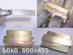
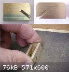
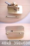
So here is the completed prototype tool and accessory guide - finished with corners rounded and all sharp edges relieved for comfort in handling.
The final dimension of the sole measures 33 mm wide by 43 mm in length.
I suppose if I had to make another it would take about a day's work without having to rush.
Now, perhaps a small fitted wooden case for the plane and the accessory guides .........
ALAMI - 4-16-2008 at 12:50 PM
Never thought of a tool as a work of art.
I live in a world (professionaly speaking) where "art" has to be expensive, where 3 different languages in a sentence are needed to meaninglessly
talk about it and where the only "manual tool" known is the iphone.
I kept looking to the photos of this tiny beautiful tool... and I felt calm.
your tool can do more than "half binding".
Thanks John,
Jameel - 4-16-2008 at 03:33 PM
What Alami said...
I say you outdid Lundberg. Now all you have to do is make one with an angled blade to cut the "ramped" rebate.
You are a valuable member here. 
jdowning - 4-16-2008 at 05:55 PM
Thanks for your kind comments ALAMI and Jameel. This little project was a low risk, low cost adventure and fun to develop and make.
Oddly enough Jameel I did wonder about the 'ramped' form of rebate when initially pondering the design and imagined that if a luthier were to
reference the guide of a tool like this not to the edge of the soundboard but to the face of the rib (ie with the plane canted at an angle to the
soundboard) then this might have been how the ramp style of rebate came about in the first place? Not sure how this would work in practice, however,
and it probably would better apply to lutes with flat rather than the rounded rib sections usually found on ouds? But this was just a passing thought.
jdowning - 6-19-2008 at 07:36 AM
For those who may have missed purchasing the mini planes when offered on sale by 'Busy Bee Tools' - 'Princess Auto' now currently has them on sale
until July 13 (while quantities last), a set of 3 for $20. These are a special purchase item so it looks as though the company will not be holding
them as a regular stock item. So, once they are gone they are gone!
They can be ordered by phone at 1-800-665-8685 or from their stores across Canada. Not sure if they will ship outside Canada.
Web site is http://www.princessauto.com
I should emphasise that it is not absolutely essential to adapt one of these planes to make a half binding tool - I used one to save a bit of time but
could just as easily have started from 'scratch'.

Clayton - 10-30-2008 at 09:50 PM
Wow... reading your tool thread was like listening to an incredible piece of music... I really enjoyed it.
Harbor Freight has a cheap set here:
http://www.harborfreight.com/cpi/ctaf/displayitem.taf?Itemnumber=97...
$11.99
These need new blades as the ones that come with them are really not worth using... but... the price!!!

jdowning - 10-31-2008 at 11:29 AM
Thank you Clayton. Glad that the topic was of interest.
Those are certainly good prices from Harbor Freight.
The prices at Busy Bee now seem to be heading in the wrong direction. They are currently offering a set of the three mini planes plus a mini square
and bevel gauge in a wooden box (but maybe a plastic box?) - normally $49.99 Can. on sale at $39.98 Can.
As noted earlier in the thread, the superior, thicker, high speed steel blade from a Lee Valley mini chisel plane will fit so can be used as a
replacement for the original blade if necessary.
jdowning - 11-26-2009 at 12:13 PM
Yet Another Alternative
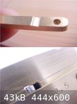
With a Lee Valley gift certificate 'burning a hole in my pocket' I decided to purchase one of the latest additions to their catalogue - a Veritas
Miniature Shoulder Plane (Cat# 05P80.01 - $31.50 Can.) as I was curious to find out if it might be adapted for use as a 'ready made' half binding
tool.
This low cost, quality precision tool is made from stainless steel and comes in a fitted box. Overall length is 63.5 mm and width 6 mm (2.5 inches X
0.24 inches). It is a scaled down miniature version of the Lee Valley Medium Shoulder Plane.
The first task - as with every new edge tool - is to hone the blade. The blade is of hardened steel with a fine ground finish so took only about 15
minutes work on an oil stone and leather strop to remove all traces of grinding marks to bring the back of the blade to a mirror finish and produce a
razor sharp cutting edge.
The blade is 0.25 inches (6.35 mm) wide so projects a little beyond the sides of the plane - so a bit more work on the oil stone was required to bring
the blade flush with the sides.
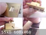
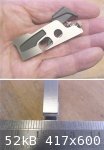
The plane was tested on a piece of quarter sawn Sitka Spruce, the edge shaped to a sound board profile. After scribing the width of the banding rebate
to 1 mm deep, with a purfling cutter, the plane was worked freehand around the edge of the test piece to remove the waste material down to the depth
of the purfling cut.
The plane was easy to control and did a pretty good job even across the grain of the wood (sharp blade essential!)
One improvement is to add a guide to eliminate any risk of the plane cutting beyond the scribed line.
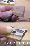
No need to modify the plane. A small piece of hard maple with a rebate cut to fit against the side of the plane is all that is required - the guide
being held in place with finger pressure alone. The depth of the rebate determines the width of cut.
So, it works and is a ready made alternative way to cut a half binding rebate if one doesn't have the time or skill to make the tool described earlier
in this thread.
Neat!
jdowning - 11-26-2009 at 12:27 PM
BTW - if you need to make your own purfling cutter do a forum search - keyword 'purfling cutter'
Yaron Naor - 11-27-2009 at 05:38 AM
Wow, very nice work! I think that building your own tools is an amazing skill and feeling
Thanks for shearing
Yaron Naor.
Jameel - 11-27-2009 at 06:46 AM
John, I bought one of these immediately with the same thing in mind. Great little plane at am amazing price.
Yaron Naor - 11-27-2009 at 07:34 AM
Hi John.
Can you please show how you sharp this tiny blade on a stone?
I find it difficult to hold on a stone and also to hone
If you have something for a Tormek sharpening system please show a picture if it is ok with you
Thanks in advanced
Yaron.
Jameel - 11-27-2009 at 08:41 AM
Yaron, I just freehand it on waterstones or abrasive paper. After polishing the back I hone the bevel by putting pressure just behind the bevel with
my index finger and pull back only on the stone, don't push. It's so small that it polishes up quickly. Just pull back, dont swirl around or push
forward.
jdowning - 11-27-2009 at 10:22 AM
I use the same technique as Jameel except that I prefer to use oil stones and a hard leather strop dressed with Lee Valley 'green' compound for final
honing.
I find the correct bevel angle by feel - first gently rocking the blade on the stone until it is felt to 'lock' on the surface. Then the blade is
drawn backwards in a single movement while maintaining this correct angle.
The blade is already finely ground as received from the manufacturer so only light pressure is required. No need to create any burrs on the cutting
edge.
It is, of course essential to remove all of the original grinding marks from the back of the blade (for the wider) spade shaped part only and from the
front edge of the bevel - other wise a weak, saw tooth cutting edge will be the result.
Thank you both
Yaron Naor - 11-27-2009 at 12:08 PM
Thanks Jameel and Jdowning,
for shearing the info, I learn so much from you!
I have a very good Japanese water stones, I will try it by hand.
Regards
Yaron.
jdowning - 11-27-2009 at 01:13 PM
Thanks for your input Yaron and Jameel
Japanese water stones should do the job even faster (and cleaner!) than oil stones. I have used both.
My hard leather strop is glued to a wooden block that can be held in a vice for ease of handling. The Lee Valley 'green' compound cuts aggressively to
a finish that probably exceeds that of the finest oil stone/water stone grits.
Good luck.
John