| Pages:
1
..
11
12
13
14
15 |
faggiuols
Oud Junkie

Posts: 285
Registered: 9-10-2014
Location: cagliari sardegna italia
Member Is Offline
|
|
to understand why I decided to do it again ...
I hope to do the decor better than before ...
|
|
|
faggiuols
Oud Junkie
Posts: 285
Registered: 9-10-2014
Location: cagliari sardegna italia
Member Is Offline
|
|
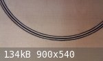
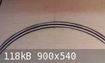
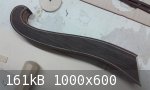
Bent the rosewood edges ....!
Now, as you see, they are tied with a strong elastic why take the correct form. In the coming days I hope to have time to glue them.
of course I will update when ready.
|
|
|
faggiuols
Oud Junkie
Posts: 285
Registered: 9-10-2014
Location: cagliari sardegna italia
Member Is Offline
|
|
good morning
I can not see the pictures that the forum members are attaching !!
I see:
[File] 37418 [/ File]
how can I see them?
I only see what I posted myself with traditional method ..
can someone help me?
and thanks to all
|
|
|
jdowning
Oud Junkie
Posts: 3485
Registered: 8-2-2006
Location: Ontario, Canada
Member Is Offline
Mood: No Mood
|
|
Unfortunately all of those past image attachments are now lost and cannot be recovered. See Mike's message under the 'News and Updates' on the forum
Home page and his earlier message on this thread.
Current images being posted are not affected. Some of the images on earlier topics have not been lost so far so if an earlier topic is of interest it
may be best to print a hard copy for your file and reference. The future of posting images by the 'traditional method' is now open to question. Mike
is currently looking into the possible alternatives.
|
|
|
faggiuols
Oud Junkie
Posts: 285
Registered: 9-10-2014
Location: cagliari sardegna italia
Member Is Offline
|
|
thanks Jdowning
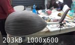
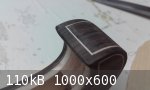
The pegbox is practically finished, but not glued. I still have to make holes for the pegs.
the interlocking-neck pegbox has yet to be finalized, but the general result satisfies me enough. everything needs to be cleaned well.
here are some pictures ..
|
|
|
jdowning
Oud Junkie
Posts: 3485
Registered: 8-2-2006
Location: Ontario, Canada
Member Is Offline
Mood: No Mood
|
|
Nicely done and good progress!
When drilling the peg holes be careful to avoid splintering of the side walls of the pegbox as the drill bit enters and exits the wood. The best drill
bits for the task are not the standard machinist drill bits but those with a brad point tip and side spurs - the brad point guides the bit so that it
does not wander and the spurs cut the wood fibres on entry so ensuring a clean hole without splintering. See attached description from the Lee Valley
catalogue - the cheaper utility style is less suitable in my experience.
To prevent wood splintering as the bit exits, stop drilling as the brad point just starts to show so leaving a small hole, withdraw the bit and then
re-drill from the outside centering the tip of the brad point into the small exit hole. Alternatively provide a piece of scrap wood clamped in place
to provide support for the bit as it exits. It is best also to provide a piece of scrap wood inside the pegbox to minimise risk of splintering as the
bit breaks through the first side of the pegbox. The diameter of the bit should be just sufficient to allow the small end of your peg reamer to enter
- the reamer then opens up the peg hole to the desired diameter. Should there be any slight splintering around the edges of a drilled hole these will
be removed during the reaming operation as the hole is enlarged in diameter.
It is more convenient to drill the holes on a drill press (using a tapered support so that the finished holes are symmetrical with the peg box centre
line) but drilling can also be done 'freehand, by eye' with care.
If a machinist style drill bit is all that is available, start by using a small diameter bit to make a 'pilot' or guide hole and then gradually
increase the hole diameter using increasing diameter bits - drilling alternately from both sides of the pegbox. The reaming operation will correct any
slight axis misalignment of the holes.
Take it slowly! Good luck.

|
|
|
faggiuols
Oud Junkie
Posts: 285
Registered: 9-10-2014
Location: cagliari sardegna italia
Member Is Offline
|
|
Thanks Jdowning
I had the suspect that the drilling operation of the pegbox was not a simple thing!
Thanks for your valuable advice.
I will do exactly as you indicated to me.
Thanks for your valuable help, without your advices my oud was definitely much worse.
When I'll do this drilling work, I will update the topic!
|
|
|
SamirCanada
Moderator
Posts: 3404
Registered: 6-4-2004
Member Is Offline
|
|
next time... better to drill the holes before assembling the pegbox. You can then drill the holes through both sides at the same time.
@samiroud Instagram
samiroudmaker@gmail.com
|
|
|
faggiuols
Oud Junkie
Posts: 285
Registered: 9-10-2014
Location: cagliari sardegna italia
Member Is Offline
|
|
Quote: Originally posted by SamirCanada  | | next time... better to drill the holes before assembling the pegbox. You can then drill the holes through both sides at the same time.
|
Dear Samir
thanks for your post.
I agree with you..
But I though that I am not a luthier, I knew that I would change the shape of the pegbox after mounting it. So I thought that making the holes before
mounting the pegbox would force me not to change slightly after the curves of the pegbox , to avoid decentralizing the holes.
That is why I preferred to do it later, knowing it would be more difficult and more dangerous.
Now I hope to do it right the job.
thanks a lot, friend
|
|
|
faggiuols
Oud Junkie
Posts: 285
Registered: 9-10-2014
Location: cagliari sardegna italia
Member Is Offline
|
|
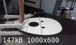
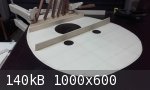
Hello to all.
an update on the work, although, as always proceed slowly.
I put some pictures of the new holes decorations, and braces in preparation.
See you soon.

|
|
|
faggiuols
Oud Junkie
Posts: 285
Registered: 9-10-2014
Location: cagliari sardegna italia
Member Is Offline
|
|
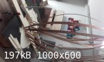
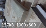
Goodmorning everyone
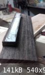
I'm pasting the braces, and I'm in big trouble.
I followed the instructions of the book by Hankey and braces are 3 mm at the center, and 4 mm to the sides.
their height is approximately 20 mm.
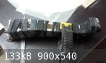
When i glue them (see technique in foto) the braces twist and do not remain permanently perpendicular to the soundboard.
I had to put a edge, but this makes glueing the more complicated.
When you have to glue the curved braces (6 - 7 - 8) everything becomes more complicated.
If anyone has suggestions I will be very grateful.
thank you all
|
|
|
jdowning
Oud Junkie
Posts: 3485
Registered: 8-2-2006
Location: Ontario, Canada
Member Is Offline
Mood: No Mood
|
|
Your 'go bars' applying pressure to the brace should bend in the same axis as the brace - not sideways as seen in the image as this will cause the
brace to topple over. Also use of hot hide glue for making the joint is beneficial as it will quickly gel and 'grab' so preventing the brace sliding
out of position as clamping pressure is applied. With hot hide glue a heavy clamping force (from using too thick and powerful 'go bars') is not
required (given precisely made joint surfaces) the glue pulling the joint surfaces together as it dries and cures.
|
|
|
faggiuols
Oud Junkie
Posts: 285
Registered: 9-10-2014
Location: cagliari sardegna italia
Member Is Offline
|
|
Thanks Jdowning
for comments, as always.
indeed the "go bars" are lateral, than the axis of the braces.
That's because I want that the braces rest on wooden board, that I placed as contrast. This piece of wood has allowed me to maintain the vertical
braces during bonding (made with animal glue).
verily section of the braces (height - 25/26 mm -- width 3 / 4mm) is too "lean," having a support of only 3 mm, can not stay upright by itself, even
putting "go bars" axis aligned with the braces's axis.
Using the piece of wood as a contrast I managed to keep upright quite the braces, but this prevented me from thoroughly clean the residual glue. Also
one of the pieces of wood are glued is slightly with residual glue, and has created me big problems for its removal.
I was wondering what precautions you need to use for keeping the vertical braces without the wood contrasting ..
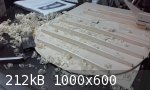
I must say that my post is a few days ago and now I'm almost finished gluing the braces. I attach you a photo. In fact, in the end, I'm pretty happy
with how I managed to solve the problems encountered. Yesterday I started modeling braces even though I have not glued the braces near the main
hole.
thank you so much
|
|
|
jdowning
Oud Junkie
Posts: 3485
Registered: 8-2-2006
Location: Ontario, Canada
Member Is Offline
Mood: No Mood
|
|
That seems to be a good efficient solution to the problem of narrow braces toppling over. You could of course cut a small bevel on the bottom corner
of the support block so providing clearance to prevent the block sticking to any glue 'squeeze out' and/or wrap the support block in plastic
'Klingwrap'.
Looking good.
|
|
|
jdowning
Oud Junkie
Posts: 3485
Registered: 8-2-2006
Location: Ontario, Canada
Member Is Offline
Mood: No Mood
|
|
Of course, also if the base of a brace is not cut at a perfect 90° angle to the side, the brace will tilt over under pressure from the clamps.
When planing the base of a brace use a 'shooting board' with the plane on its side to ensure accuracy. See here on post dated 2-8-2009
http://www.mikeouds.com/messageboard/viewthread.php?tid=8565
|
|
|
faggiuols
Oud Junkie
Posts: 285
Registered: 9-10-2014
Location: cagliari sardegna italia
Member Is Offline
|
|
| Quote: Originally posted by jdowning | That seems to be a good efficient solution to the problem of narrow braces toppling over. You could of course cut a small bevel on the bottom corner
of the support block so providing clearance to prevent the block sticking to any glue 'squeeze out' and/or wrap the support block in plastic
'Klingwrap'.
Looking good. |
In fact, after the first few errors, I used a piece wood with rounded edges! for this I managed to solve the problem.
sometimes I do the right thing !!
|
|
|
faggiuols
Oud Junkie
Posts: 285
Registered: 9-10-2014
Location: cagliari sardegna italia
Member Is Offline
|
|
| Quote: Originally posted by jdowning | Of course, also if the base of a brace is not cut at a perfect 90° angle to the side, the brace will tilt over under pressure from the clamps.
When planing the base of a brace use a 'shooting board' with the plane on its side to ensure accuracy. See here on post dated 2-8-2009
[url]http://www.mikeouds.com/messageboard/viewthread.php?tid=8565 |
[/url]
I had not thought about the perfection of the contact surface to be bonded and its perfectly perpendicular.
I used technique similar to the one that you suggest in your post, however, instead of the plane I used a wooden block perpendicular and I polished
the surface bonding holding the braces resting on the perpendicular block.
it could be that there were flaws in this work. but they are now no longer able to control. I though I still incollre the braces on the hole (see
photo). I'll check when I will prepare better these last two braces.
I hope I explained in english!
|
|
|
jdowning
Oud Junkie
Posts: 3485
Registered: 8-2-2006
Location: Ontario, Canada
Member Is Offline
Mood: No Mood
|
|
A sanding block that is straight and square can certainly be used on a shooting board in place of a long plane where only small amounts of material
need to be removed.
Some will make use of a metal carpenter's/builder's level for this purpose. These levels are long, straight and accurately machined on all sides (or
should be!). Just glue a strip of abrasive paper along one edge. Use a soluble glue that may be removed when the abrasive strip is worn and needs
replacement.
|
|
|
faggiuols
Oud Junkie
Posts: 285
Registered: 9-10-2014
Location: cagliari sardegna italia
Member Is Offline
|
|
Thanks Jdowning
could you kindly attach a photo of the "metal carpenter's / builder's level", because I was not able to understand well the type of object.
I understand that it should be an object of daily use for a carpenter .. (?), but I do not understand what object is. I think I lost something in the
translation!
thanks so much as always
|
|
|
jdowning
Oud Junkie
Posts: 3485
Registered: 8-2-2006
Location: Ontario, Canada
Member Is Offline
Mood: No Mood
|
|
These levels are used by builders to ensure construction is level and vertical. They are also called 'spirit levels' or 'bubble levels' or 'box
levels' or 'I-beam levels'. They come in various shapes and sizes made from wood, plastic or metal. The ones most suited for use on a shooting board
are the metal straight sided 'I-beam' type with an aluminium frame of 'I' section about 60 cm or so in length. The level is placed on its side and the
abrasive paper is glued to the base surface of the level.
I do not have images and am no longer set up to post images anyway - but just do a Google search for 'I-beam level' images and I am sure that you will
recognise the tool that I am referring to. The basic levels are not expensive new but can often be picked up cheaper at yard sales. They are also
useful for any home repair projects!
|
|
|
faggiuols
Oud Junkie
Posts: 285
Registered: 9-10-2014
Location: cagliari sardegna italia
Member Is Offline
|
|
Of course!
I know very well the level of which you speak.
I have one in my lab quite nice.
I was not sure I understand exactly the tool that you mentioned in your post.
I'll definitely try to ursare it as you say!
thank you so much.
As soon as I further upgrade I will make a new post
|
|
|
faggiuols
Oud Junkie
Posts: 285
Registered: 9-10-2014
Location: cagliari sardegna italia
Member Is Offline
|
|
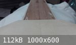
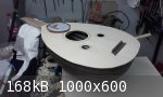
Hello to all
I'm back with my realization's problems of my first oud!
the problems are:
1 - I made the braces n. 6 - 7 - 8 curved, as written in the book of Hankey. This has, obviously, done arched soundboard after that I glued the
braces.
Now the soundboard no longer coincides with the edge of the bowl (see foto).
Must I force gluing the soundboard to bowl in the rear block?
2 - I cut the braces before mounting the soundboard on the bowl. then I tried to cash the soundboard in the bowl in his position but I unfortunately
found that there is a small misalignment of the soundboard axis compared to the bowl axis! it's normal?? if you cut the end of the braces to remove
the problem, then i think that some braces will not touch most the bowl and the connection will be bad!!
what do you think?
I am attaching two pictures that clarify the problems better than my bad english .
the last picture is for an update on the work.
thanks to those who want to give me some advice!
|
|
|
faggiuols
Oud Junkie
Posts: 285
Registered: 9-10-2014
Location: cagliari sardegna italia
Member Is Offline
|
|
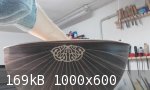
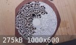
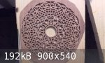
Hello everyone
I would like to know your own opinion!
I'm doing rosette and thinking to smooth the sharp edges of the cuts made by the jigsaw, both to improve the aesthetics of the work that has defects,
to soften the effect of the rosette.
I saw that all the rosettes of oud I've seen are with the edges at 90 °, that is as they come out from the cut.
what do you think?
thank you all
|
|
|
jdowning
Oud Junkie
Posts: 3485
Registered: 8-2-2006
Location: Ontario, Canada
Member Is Offline
Mood: No Mood
|
|
The way I build lutes is to cut the sound board oversize and first align sound board centre line to bowl/neck centre line then marking the bowl
outline in pencil on the underside of the sound board for reference. The brace positions are then marked and the braces glued in place. The braces are
cut oversize in length and are trimmed after gluing to the sound board. The ends of each brace are then reduced in depth by paring with a chisel until
the depth at the outside is about 5 mm. The ends of the braces are then trimmed to the bowl profile (allowing for rib thickness of the edge of the
bowl) using a fine razor saw/sharp chisel - test fitting the sound board to bowl as brace trimming progresses until a close fit of the brace ends to
sides of the bowl is achieved with everything in position and in alignment.
I judge the correct fit of each brace and by 'feel' - slight rubbing noise heard at each brace end as the sound board is placed in position. If an
error is made in trimming the end of a brace then veneer can be glued to the end of the brace to fill any gap or a small veneer patch can be glued to
the bowl at the location of the end of the brace.
The bridge position and alignment can then be established using a template as seen here:
http://www.mikeouds.com/messageboard/viewthread.php?tid=8488&pa...
As your bridge is already glued in position it may now be best to check and correct any misalignment with sound board in place (if significant) using
a similar template. It is of course important to be sure that when the sound board is glued in place that the strings, when fitted, will all be
correctly aligned over the fingerboard.
When gluing the sound board, the first part to be clamped is the area over the neck block. This will flatten any residual sound board curvature at
that location.
That is a very intricate and ambitious rosette design to cut as a first attempt - congratulations with your work so far! To avoid breakage of the fine
elements of the design, it is always best to cut from the centre of the rosette outwards - although if you are using a power jigsaw (rather than with
a hand saw) this is perhaps not quite so critical as the workpiece is well supported during sawing. In my opinion - given the complexity of the design
- I would just leave everything with crisp sharp 90°edges as it comes off the saw (and so ensure that nothing gets broken). If some clean up of the
cut edges is necessary this can be done (carefully!) with a 'needle file' or sharp scalpel. If any bits break off accidentally during sawing be sure
to save them and glue them back in place as work proceeds. Some imperfections may be forgiven and likely will never be noticed once the work is
complete.
|
|
|
faggiuols
Oud Junkie
Posts: 285
Registered: 9-10-2014
Location: cagliari sardegna italia
Member Is Offline
|
|
Dear Jdowning
thanks a lot, as always, for your valuable explanations.
about the soudnboard and braces slightly wrong, I wonder if it is better to smooth the end of braces and bring the axis of the soundboard in the
correct position, or, since the error is very low, leave everything as it is now?
the way to correct the braces I find it difficult, because I do not really know what brace is wrong, and therefore it seems to me that, perhaps,
further got worse the error.
I followed the book of Hankey and I made as explained in the book.
thanks for the link about setup of the bridge! I studied well this topic, but I had missed the point where you explain how to paste the bridge.
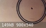
about the rosette it was finished a few days ago. I am attaching the picture after removing the paper pattern.
To stiffen the wood I glued behind it a maple sheet to be 0.5 mm. and I'm glad I did. This allowed me to cut with confidence the project, but now I am
anxious for the Maple removal that I will very carefully with sandpaper.
the rosette have the cuts "dirty", and I would like to improve them with my scalpel, or with small strips of sandpaper 180 to pass in the cuts.
as you can see from the picture, it must be corrected much!
I hope that, ultimately, it will be nice!
|
|
|
| Pages:
1
..
11
12
13
14
15 |


