| Pages:
1
..
4
5
6
7
8
..
16 |
jdowning
Oud Junkie

Posts: 3485
Registered: 8-2-2006
Location: Ontario, Canada
Member Is Offline
Mood: No Mood
|
|
Another small interlude.
I plan to measure the final thickesses (the thickness will vary a little from area to area) across the entire surface of the finished soundboard. This
is mainly for record purposes and is not essential.
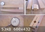
The measurement will be made with a luthiers caliper. 'Luthiers Mercantile International' at http://www.lmii.com sell calipers of this kind - nice tools but costing around $150 US. So I decided to make my own - not as fancy but one that
will do the job.
The heart of this measuring device is a dial (or deflection) gauge made in China costing around $15 US or less (but good quality nevertheless) -
available from most engineering tool suppliers as well as Lee Valley Tools. They come in various dial sizes and travel as well as being graduated in
Imperial or metric graduations. (This gauge, for example, has a 2inch dial, 1 inch travel and graduations in thousands of an inch).
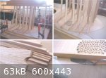
The frame of the calipers has been made from 7/8 inch (22 mm) thick straight grained pine - the two arms being joined together with a spacer block and
open ended mortice and tenon joints. This type of joint is easy to accurately cut on a router table. The image shows the spacer block prior to
trimming the tenons and finishing. The throat of the caliper is 9 inches (23 cm) so will cover sound boards up to 18 inches wide. The dimensions can
be varied according to personal requirements and whim. The design principle here is "if it looks right it is right"!
The dial gauge is clamped securely in place on the upper arm with two machine screws. A saw cut through the gauge mounting hole provides some local
flexibility for clamping.
The frame has been assembled using brand "Gorilla" polyurethane glue. No particular reason other than I wanted to try it. Any good cabinetmaker's wood
working glue would do just as well.Once the glue has cured, the frame will be trimmed and finished.
The calipers will be clamped in a vice in use allowing both hands to be free for manipulating the sound board.
|
|
|
SamirCanada
Moderator
Posts: 3404
Registered: 6-4-2004
Member Is Offline
|
|
Thanks a lot for the thickness jig John!
I will use this setup from now on! I have been dreading buying a professional one also.
I am following the updates to this project with great enthusiasm by the way.
I just cant post as often now days since I no longer have acces to the forums from work! Bloody I.T. security!!
|
|
|
jdowning
Oud Junkie
Posts: 3485
Registered: 8-2-2006
Location: Ontario, Canada
Member Is Offline
Mood: No Mood
|
|
Thanks Samir
Why not go 'mobile' and do the forum on your lunch break?! Apparently
A.T &T are touting a mini laptop (Acer Netbook) for only 50 bucks U.S. - the catch? - you must sign up for a two year contract ($1500 US ?).
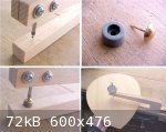
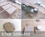
The calipers were completed this morning by first trimming and finishing the frame - rounding off sharp corners etc. The final step is to fit an
'anvil' to provide a raised, point contact surface with the plunger of the dial gauge. The dial gauge is first mounted and clamped in place and the
plunger carefully pressed down to make a slight indentation in the lower arm. This indentation in the wood is the exact position for the centre line
of the anvil. The anvil may be made from metal or wood and should, ideally, be dome shaped. Many items of hardware might be adapted to serve as an
anvil - dome headed rivets, small carriage bolts, ball bearings (or even a piece of wooden dowel rounded into a dome) etc - all available, off the
shelf, from hardware stores. Here I have used a brass, dome headed, upholstery nail together with a hard rubber cabinet door 'bumper' that I happened
to have in stock. The nail/bumper combination were hammered into place by removing the dial gauge and using a wooden dowel as a punch - the dowel
diameter being a close sliding fit in the dial gauge mounting hole as a guide.
Before use of the calipers, the dial gauge must be adjusted to read 'zero' when the plunger tip is in contact with the anvil. A rough adjustment can
be made by positioning the dial gauge in the frame before clamping it in place. Fine adjustment is then made by rotating the scale of the gauge to the
zero mark.
In use, the caliper is mounted in a bench vise and the sound board manipulated with both hands. The sound board should be held level to obtain the
most accurate readings.
The plunger of the dial gauge is spring loaded so this provides the light pressure necessary for an accurate reading but is an insufficient load to
deflect the frame and cause a false measurement.
All of my accurate measuring tools, calipers, dial gauges, micrometers etc are in standard Imperial units of thousands of an inch because those are
the units that I have always used for working metals - lathe work etc. However, I prefer to use Metric measurements for luthier work. So - when using
an Imperial standard dial gauge for instrument making - all that is necessary is to make up a handy chart converting the Imperial readings to metric.
This chart needs only be in steps of 0.1 mm.
A simpler solution, of course, would be to use a Metric dial gauge.
|
|
|
jdowning
Oud Junkie
Posts: 3485
Registered: 8-2-2006
Location: Ontario, Canada
Member Is Offline
Mood: No Mood
|
|
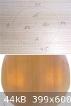
Work on final thicknessing of the soundboard - using scraper blades - has progressed to completion. Thickness is 1.5 mm in the central part of the
soundboard increasing to 1.8 mm around the edges.
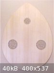
As the sound holes are to be 'cut in' - like a lute - the area covered by each sound hole must be reduced further in thickness to about 1 mm (0.040
inch). At present only two sound holes are to be cut - as represented by the oud engraving - but a third sound hole may be added later. Using a
scraper blade, and working around the sound hole centres pierced in the sound board, the thickness was carefully reduced - regularly plotting the
reduction in thickness as work progressed. The thickness calipers proved very useful for this operation.
An assessment of the relative sound board thickness variations can be determined by holding the sound board up to a strong back light.
|
|
|
Jameel
Oud Junkie
Posts: 1672
Registered: 12-5-2002
Member Is Offline
Mood: No Mood
|
|
Great reading, John. Nice caliper too. Ditto on the metric for ouds too. I do the same. I've been meaning to make one of these calipers for some time.
I picked up the digital caliper from Lee Valley for the project. It swaps from imperial to metric at the touch of a button. Very handy.
|
|
|
jdowning
Oud Junkie
Posts: 3485
Registered: 8-2-2006
Location: Ontario, Canada
Member Is Offline
Mood: No Mood
|
|
Thanks Jameel. The Chinese made precision measurement tools can be great value today.
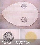
The next stage in cutting the sound holes is to glue a paper pattern of the rosette design to the underside of the sound board. A traditional 16th C
lute rosette design has been selected as this clearly has Arabic geometric design origins - as well as the six pointed star motif represented in the
oud engraving. In order to match the sound hole diameter it was necessary to reduce the scale of the original lute pattern to 78%. This was done on an
ink jet printer using 20 lb paper - the ink is water soluble so the paper pattern was waterproofed with a coating of orange shellac. The paper pattern
was glued to the sound board with thin hot hide glue - applied to the sound board not the paper (which would curl up and be difficult to handle). To
ensure that each pattern was fully glued, they were ironed over with a warm iron.
To reinforce and harden the front face of the rosette in preparation for the cutting operation, the soundboard over the sound hole area was coated
with shellac. The shellac will be removed later after completion of the rosettes.
|
|
|
jdowning
Oud Junkie
Posts: 3485
Registered: 8-2-2006
Location: Ontario, Canada
Member Is Offline
Mood: No Mood
|
|
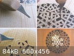
The rosette cutting - or piercing - work is done with a fine chisel cutting directly through the pattern on the back of the sound board with the front
face of the sound board supported on a hard, flat, smooth surface. A piece of 3mm thick tempered 'hardboard' makes an ideal surface.
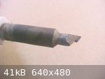
The chisel has been made from a broken hacksaw blade - glued into a wooden handle with epoxy cement - and ground into a narrow profile as shown in the
images. The width is just under 2 mm. The cutting edge is honed to a fine bevel and is curved along its length. The cutting action is to stab
downwards through the sound board thickness at each corner of the pattern and then to extend the cut by rotating the chisel backward. Slicing cuts
(using a standard scalpel or craft knife) are not practical due to the hard/soft nature of the grain of the Spruce - making the knife impossible to
control.
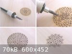
Cutting starts at the centre of the rosette working progressively outwards. Each piece, when correctly cut, will 'pop' out (from front to back) of its
own accord - it must not be forced to avoid the risk of breakage of the delicate wood tracery. I do not bother to try to remove little 'whiskers' of
wood left behind (the rosette is very fragile and easily damaged) preferring to leave everything as it comes 'off the chisel' - 'warts and all'!
Every few cuts, the chisel should be honed on a leather strop (dressed with Lee Valley 'green' compound) to keep the cutting edge razor sharp -
essential for clean cuts and to avoid breakage of the wood.
It takes me about two hours to pierce a sound hole rosette of this diameter (70 mm). It helps to take a break from the task every so often! Boring but
satisfying in the end!
|
|
|
jdowning
Oud Junkie
Posts: 3485
Registered: 8-2-2006
Location: Ontario, Canada
Member Is Offline
Mood: No Mood
|
|
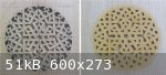
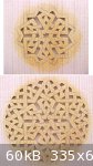
Here is a pierced but incompleted rosette as viewed from the underside of the sound board as well as on the front face.
The next step is to emboss the front face of the rosette to emphasise the interlacing elements of the pattern.
|
|
|
SamirCanada
Moderator
Posts: 3404
Registered: 6-4-2004
Member Is Offline
|
|
NICE work!!
thanks John.
|
|
|
jdowning
Oud Junkie
Posts: 3485
Registered: 8-2-2006
Location: Ontario, Canada
Member Is Offline
Mood: No Mood
|
|
Thanks Samir.
As 'cut in' sound holes must be completed before a sound board is braced, a final decision must be made about the sound hole configuration - two sound
holes or three? The oud engraving represents only two but perhaps a third, centrally placed sound hole was omitted by the engraver for clarity?
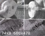
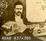
The attached low resolution image shows an unidentified picture of an early oud (10th C Persian?). Note the two large sound holes placed low down near
the bridge as well as a smaller sound hole located near the fingerboard. (Note also the sickle shaped peg box and soundboard edge banding).
For comparison, the other image shows an early European (15th C) fretted lute with a single large sound hole placed, low down, near the bridge, with a
smaller sound hole located closer to the fingerboard.
Edited 27 November 2009 to include higher resolution image of the oud.


|
|
|
jdowning
Oud Junkie
Posts: 3485
Registered: 8-2-2006
Location: Ontario, Canada
Member Is Offline
Mood: No Mood
|
|
Here is another example of two early 15th C lutes (Florentine) each with a large sound hole placed near the bridge and a small sound hole located
higher towards the finger board. Note also the lack of frets, the five courses, the ribbed construction of the bowls and sloping shoulder of the neck
at the neck joint. Definitely oud like features! Note also the Arabic geometry of the large 'cut in' sound holes and the similar geometry of the
reduced diameter sound hole.
I would speculate, from this limited information, that some early oud/lutes had either two sound holes or a single sound hole located near the bridge
but with a smaller diameter sound hole located higher up on the sound board - the equivalent total sound hole areas being the same in each case.
|
|
|
jdowning
Oud Junkie
Posts: 3485
Registered: 8-2-2006
Location: Ontario, Canada
Member Is Offline
Mood: No Mood
|
|
So, rather than adding a third large diameter central sound hole (as used in creating the geometry of the oud soundboard) which would have
significantly reduced the sound board area, I have chosen to add a small diameter sound hole fitted between braces five and six.
It so happens that the total area of the three sound holes is within 7% of the area of the single large sound hole taken from the oud sound board
geometry.
So the little sound hole is now 'cut in'. No turning back now!
|
|
|
DaveH
Oud Junkie
Posts: 526
Registered: 12-23-2005
Location: Birmingham, UK
Member Is Offline
Mood: No Mood
|
|
Well, I've no idea what the most historically authentic arrangement is but aesthetically I think you've hit the jackpot. Very fine work. It will be
interesting to see how this sounds, and, of course, it would be very interesting to be able to compare both configurations, but unfortunately
that's too much to ask.
|
|
|
jdowning
Oud Junkie
Posts: 3485
Registered: 8-2-2006
Location: Ontario, Canada
Member Is Offline
Mood: No Mood
|
|
Thanks DaveH. There are at least 8 historical possibilities for sound hole configuration in ouds/lutes plus their variations in placement on the sound
board. However, a large central sound hole together with two medium sized sound holes does not appear to be one of them and it does not 'feel right'
for this instrument either (excessive sound hole area).
I hope to be able to make some comparisons with this arrangement by temporarily blocking off the small sound hole with a thin aluminium plate, taped
in place, just to see if that makes any significant difference.
Here, for information, is the image of a Tunisian four course fretted oud (oud arbi?) previously posted on the forum that retains the two large/one
small, sound hole configuration but positioned as a group high up on the soundboard. The rosettes on these instruments were often 'cut in'
apparently.
This close grouped triple rosette arrangement was also to be found on some of the larger lutes of the 16th/17th C.
On the subject of historical sound hole configuration I shall next post a brief research article on the subject - for what it is worth - that I wrote
for FoMRHI in April 1979 and which is listed in the bibliography of Robert Lundberg's book "Historical Lute Construction" so it may still be of some
general interest.
|
|
|
jdowning
Oud Junkie
Posts: 3485
Registered: 8-2-2006
Location: Ontario, Canada
Member Is Offline
Mood: No Mood
|
|
Here is the article "Sound hole Migration in the Development of the Lute" FoMRHI 15, April 1979, pp 38-41.
It would be interesting to repeat this investigation for historical oud sound hole configurations through a study of the surviving paintings and
miniatures - although the earliest lutes depicted in the European iconography - prior to the 16th C - are likely similar if not identical to ouds of
the same time period.
|
|
|
jdowning
Oud Junkie
Posts: 3485
Registered: 8-2-2006
Location: Ontario, Canada
Member Is Offline
Mood: No Mood
|
|
The final step in cutting the rosette (shamsa) is to emboss the front face to create an illusion of the interlacing pattern. Traditionally this was
done by lute makers by means of chip carving using small chisels and knives. Wood engraving or block cutting chisels cannot be used for this work as
the rosette is too thin and delicate. I use a scalpel to slice shallow 'V' grooves to about 0.5 mm deep in the tracery of the rosette (not much
material is left after this - a delicate and time consuming operation). However, as this is an experimental project and as my eyes and steadiness of
hand are not quite what they once used to be, I have decided to undertake the embossing work not by carving but by wood burning using pyrographic
techniques - a hot blade being used to scorch grooves in the wood to create the embossed pattern. Pyrography is a very ancient technique - at least
3000 years old - for producing incised patterns in wood or other materials. It is a technique that was used to decorate the ancient harps of Ireland
and Scotland but to my knowledge has never been used historically in the creation of lute rosettes. So here is a first! The black, charred wood lines
should create an interesting contrast - hopefully.
First of all, the incised lines are marked on the rosette in soft pencil as a guide. The pattern is complex so it is easy to make a mistake and
mistakes are not an option at this stage!
|
|
|
jdowning
Oud Junkie
Posts: 3485
Registered: 8-2-2006
Location: Ontario, Canada
Member Is Offline
Mood: No Mood
|
|
The pyrography 'pen' that I am using is a low cost tool purchased from a local hardware store - essentially just a low wattage (30 Watt) electrical
soldering iron with a chisel shaped tip. Better pyrography units with temperature control and a variety of tip shapes - used by bird carvers - are
quite expensive but are likely more controllable and would do a more precise job.
A steady hand and very little pressure on the pen - just a light touch - is required as it can be easy to burn through the wood especially in the
direction of the grain.
The end result is not quite as neat and precise as I would have liked but is sufficient to prove this technique as viable - and a lot faster than chip
carving. I just went ahead and did the work but a bit of practice before hand might have been of benefit!
|
|
|
jdowning
Oud Junkie
Posts: 3485
Registered: 8-2-2006
Location: Ontario, Canada
Member Is Offline
Mood: No Mood
|
|
As an after thought, the tip of the pyrographic pen has been reduced to about half its original length by filing. This allows the pen to work more
precisely. Too late for work on the rosettes - now essentially completed - but useful for final 'touch up' of the details.
|
|
|
jdowning
Oud Junkie
Posts: 3485
Registered: 8-2-2006
Location: Ontario, Canada
Member Is Offline
Mood: No Mood
|
|
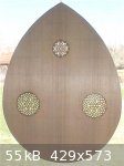
Et voila! - the completed (but unbraced) soundboard.
We have been experiencing unusually dry Spring conditions of low relative humidity so this is a potential 'window of opportunity' to complete the
bracing of the soundboard. However, the rain clouds have already moved in so this may no longer be a possibility - in which case, barring of the
soundboard will have to be postponed until dryer conditions prevail towards the end of this year. No problem - lots more work to be done.
|
|
|
jdowning
Oud Junkie
Posts: 3485
Registered: 8-2-2006
Location: Ontario, Canada
Member Is Offline
Mood: No Mood
|
|
With cool outside temperatures and the wood stove in operation, relative humidity in the kitchen dropped to 50% overnight so the sound board was
braced this morning. This may be the last chance before hot, wet weather starts to move in this weekend.
The braces have all been cut and planed to an equal height and thickness of 15 mm X 4 mm but will be trimmed, as necessary, at a later stage after
being glued in place. The braces are made from the same well seasoned Sitka Spruce stock as the sound board. Unlike the braces of modern ouds, the
grain of the wood runs horizontal rather than vertical in the brace cross section. This grain direction is typical of 16th C lute practice so may, at
one time, have applied to early ouds as well. The horizontal grain provides a better gluing surface to the sound board and may have some acoustical
advantage as yet undefined.
The clamping of the braces was done using my 'GoBar' unit. I have had mixed results with this tool in the past. It has worked well with the wider
braces found in early guitars, vihuelas etc. but less so with narrow lute braces. The slightest misalignment of the 'gobar' tends to tilt the brace
sideways. This is particularly the case with 'gobars' of round cross section that will bend in any direction.
In an effort to correct this problem, a set of 18 'gobars' (enough for clamping 6 braces at one time) were made from relatively straight grained,
seasoned Ash wood. The 'gobars' were made flat in section (20 mm wide X 3 mm thick) - cut square at one end and filed to a smooth rounded profile at
the other to engage the top of the brace when sprung into place. The intent is to ensure that the 'gobar' will bend only in the direction of the
length of a brace and so eliminate any sideways forces that would cause a narrow brace to tilt sideways.
Another potential problem with the 'gobar' system is that the base and top of the frame must be made rigid enough to minimise any deflection due to
the cumulative loading presented by the 'gobars when sprung into place. This loading can be substantial, sufficient cause undesirable bending of the
frame - not such a problem when clamping two (or three) braces for an early guitar but more so when many more braces are to be clamped at one time.
The braces were glued to the sound board with hot hide glue. Each brace was first heated before application of the glue in order to increase the brief
time available before the glue 'gelled' and became unworkable. Working as quickly as possible, the braces were glued and clamped in place. However,
the flat section 'gobars' did not prevent three of the braces from tilting slightly sideways under clamping pressure. I was also uncertain about the
consistency of the glue which I felt, in retrospect, was insufficiently diluted or 'watered down' for the task.
So, nothing for it but to remove the braces and start again! Not a big problem when using hot hide glue. Using a low cost, thin, stainless steel
artists spatula (4 for $10 Can. from Lee Valley), the glue at both sides of each brace is first moistened with a brush dipped in hot water. An
electric hair dryer, at maximum heat setting, is then used to heat the glued joint while the spatula is carefully worked into the joint at one end to
separate it. At this stage water is then brushed only onto the blade of the spatula which is gently pushed further into the joint (no forcing!), as
heat is applied, until the brace completely separates from the sound board.
If relative humidity drops below 55% within the next few days, the braces will be cleaned of glue and used for for a second gluing attempt. If the
'gobar' system does not work satisfactorily then the braces will be clamped individually using a clamping brace.
If prevailing humidity levels exceed 55% then all that can be done at this point in time will be to brace the less critical sound hole rosettes.
Thank goodness I don't have to make instruments for a living!
|
|
|
Peyman
Oud Junkie
Posts: 496
Registered: 7-22-2005
Member Is Offline
Mood: Mahoor
|
|
The rosette cutting technique is really neat. I might look into this wood burning thing. Also thanks for the caliper post.
|
|
|
jdowning
Oud Junkie
Posts: 3485
Registered: 8-2-2006
Location: Ontario, Canada
Member Is Offline
Mood: No Mood
|
|
My pleasure Peyman.
|
|
|
WFBustard
Oud Addict
Posts: 31
Registered: 3-7-2009
Member Is Offline
Mood: No Mood
|
|
Very Nice, Will you be adding further decoration to govern the order of the top?
The small centre rose looks so alone there.
|
|
|
jdowning
Oud Junkie
Posts: 3485
Registered: 8-2-2006
Location: Ontario, Canada
Member Is Offline
Mood: No Mood
|
|
No - in order to replicate the oud represented by the engraving as closely as possible, the only 'decoration' on the soundboard will be on the bridge
and in the sound board edge banding.
Ibn al-Tahhan al-Musiqi in the 14th C. wrote that "the best ouds are uncarved and undecorated and are made from one kind of wood" (meaning the wood of
the bowl, I assume). He goes on to write that "If it is desirable that it should be decorated with ebony, this should be as light and thin as
possible, and sparsely used" (Dr. G.H. Farmer translation).
So the top of the bridge and the soundboard edge banding on this project will be thin (about 0.5 mm thick) and of contrasting ebony/boxwood tiles (as
indicated on the bridge in the engraving).
As wet Spring weather is currently moving through this region (100% relative humidity outside - 60% inside the workshop today) no progress can be made
on any assembly work until drier conditions prevail.
The "cut in" rosettes are very fragile at this stage so must be reinforced. This was achieved traditionally in 16th C lutes by gluing thin strips of
sound board wood underneath each rosette across the sound board wood grain.
The reinforcement strips have been prepared from scraps of sound board material - thinned to 1.5 mm thickness and 2.5 mm depth - using a purfling
thicknesser. This simple tool is made by cutting grooves of varying depths in a block of Maple wood (I used a router to make the grooves). The strips
are then all brought to the desired uniform thickness and depth by pulling them through the selected groove while holding a block plane at an angle on
the top of the purfling thicknesser (the plane is held stationary throughout this operation).
The image shows the strips, arranged as they will be glued to the back of the rosette. Hot hide glue will be used for this operation so the strips
will be held flat and in place - until the glue is fully cured - using 'cauls' made from chipboard to which a soft, flexible synthetic rubber facing
has been attached with double sided adhesive tape (The rubber facing is a cheap, 'non slip' underlay used for carpets). The 'cauls' will be held in
place using lead weights (wrapped in masking tape to eliminate all possibility of lead poisoning when handled). Better safe than sorry.
The front face of each rosette will then be further consolidated and strengthened by painting the surfaces with thin Shellac that will soak into the
wood. Shellac makes quite a good adhesive and will reinforce any otherwise invisible cracks that may exist in the rosette piercing work.
|
|
|
ALAMI
Oud Junkie
Posts: 643
Registered: 12-14-2006
Location: Beirut
Member Is Offline
Mood: No Mood
|
|
I was recently talking with a luthier, he was complaining about how they got all stuck with the Nahats and/or Fadel way of designing and making ouds,
customers won't easily accept any other approach whether "new" or "old".
What I love about this project, beyond the amazing purity, simplicity and precision of the techniques and the tools, is the free thinking that's
behind.
John went through extensive research related to every aspect of oud making history and available documents, he asked a lot of questions but finally
decided to make "His" synthesis and his interpretation regardless of all preconceived ideas. A wise mix of science and intuition, this is typically
called: creativity.
Is it the exact medieval oud?, I believe that it is probably the closest replica ever made but I know for sure that it is an amzing project, thanks
John for taking us with you on this enlightening journey.
|
|
|
| Pages:
1
..
4
5
6
7
8
..
16 |


