| Pages:
1
..
10
11
12
13
14
..
16 |
jdowning
Oud Junkie

Posts: 3485
Registered: 8-2-2006
Location: Ontario, Canada
Member Is Offline
Mood: No Mood
|
|
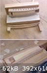
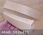
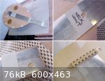
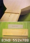
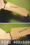
Having tapered the upper inside surfaces of the pegbox, the bottom of the peg box has been trimmed to size. This was done on a band saw - holding the
peg box square and at the correct angle on the drilling jig. The band saw cuts through the base of the jig in this operation but - no problem - the
jig is disposable - for "once off use" - and will eventually end up on the wood stove.
Having trimmed the base of the peg box to size, the base of the drilling jig has been removed allowing the jig to be held in a vice. This is now used
to hold the peg box for final smoothing and finishing of the curved bottom edges prior to fitting the peg box back plate. The taper of the jig
mounting block holds the peg box securely during this final operation.
|
|
|
jdowning
Oud Junkie
Posts: 3485
Registered: 8-2-2006
Location: Ontario, Canada
Member Is Offline
Mood: No Mood
|
|
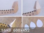
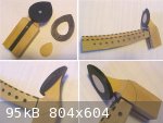
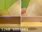
The question about how to interpret the enigmatic peg box finial represented in the engraving is still not fully resolved so it has been decided to
proceed with the design previously posted (see page 9).
In order to better visualise the contours and geometry of the finial - as well as gaining an appreciation of the best way to handle the carving work
and assembly - a 'mock up' of the finial has been made using soft pine and cardboard.
The material of the body of the finial has yet to be decided upon - ash, ebony, boxwood (or even pear wood stained black perhaps) - but minimising the
weight is an objective.
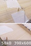
A curved plate of ebony with Persian boxwood inlay (all about 3mm thick overall) will be mounted on the finial block. The outline of the plate will be
pear shaped - identical to the geometry of the sound board. In order to arrive at the best proportion for the plate, several models of different size
have been cut from thin card and tried out as part of the mock up assembly.
"If it looks right it is right" (to my eye) is the final criterion!
|
|
|
jdowning
Oud Junkie
Posts: 3485
Registered: 8-2-2006
Location: Ontario, Canada
Member Is Offline
Mood: No Mood
|
|
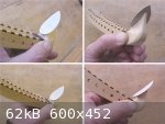
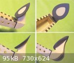
The attached image shows the trial and error shaping of the finial in order to arrive at the 'best' geometry. Here it can be seen that quite a bit
more material can usefully be removed from the finial block to reduce weight and slim down the proportions.
One idea for material is to use a piece of Ash selected so that the wood grain follows the profile of the finial block. Just a thought at this stage,
however.
|
|
|
jdowning
Oud Junkie
Posts: 3485
Registered: 8-2-2006
Location: Ontario, Canada
Member Is Offline
Mood: No Mood
|
|
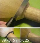
The peg box back-plate has been fitted and the peg box trimmed and finished to size. The peg box is now ready to be be fitted to the neck and to
receive the finial.
The back-plate has been made from a piece of the Ash rib stock - 2 mm thick, hot bent to the peg box curve and glued in place.
The peg box ends have been trimmed to size using a razor saw to avoid any danger of chipping the veneer and banding (the band-saw blade is too coarse
for this work). After trimming, the end grain cut faces have been smoothed flat on a fine sanding block.
The body of the peg box finial will be made from box wood with a 3 mm thick central spine of ebony and the 'tear' shaped plate from ebony with a
central inlay of box wood.
|
|
|
jdowning
Oud Junkie
Posts: 3485
Registered: 8-2-2006
Location: Ontario, Canada
Member Is Offline
Mood: No Mood
|
|
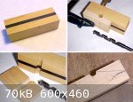
The first step in making the finial is to prepare the blank for the finial body. This is a 'sandwich' of Persian boxwood with a central core of
African ebony. The blank has been made well oversize - wasteful but necessary for ease of handling during the preparation and carving stages of the
finial body.
The small radius inner curve of the finial body has been cut with a spur bit woodworking drill to provide a clean cut result. A 'sacrificial' block of
hardwood was clamped to the blank to provide support for the drill - the cut being made with everything clamped securely and square in a drill press
running at lowest possible speed and with slow feed.
The rough profile of the finial body has been marked out ready for preliminary carving.
|
|
|
jdowning
Oud Junkie
Posts: 3485
Registered: 8-2-2006
Location: Ontario, Canada
Member Is Offline
Mood: No Mood
|
|
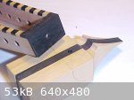
The upper part of the finial body has been shaped close to finished dimensions using sanding drums in a drill press. For final finishing to size the
finial body will first be registered - correctly aligned - to the peg box end with a small piece of hardwood dowel inserted into pre-drilled holes.
This will also facilitate accurately gluing the awkward shaped completed finial to the peg box.
The finial cap - 'tear drop' shaped to the same geometry as the body of the oud - will be made from ebony with a matching 'tear drop' inlay of
boxwood. The cap will be made in two parts glued together - a base in solid ebony and the upper ebony/boxwood inlay.
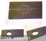
The first step is to cut the hole for the inlay starting with a stick of ebony (for ease of handling) about 6 mm thick. After laying out the profile
of the inlay, a 3/4 inch (19 mm) diameter hole was first clean cut through the ebony. This was done using a Forstner drill bit in a drill press at low
speed/ low feed - with the work securely clamped to the drill table (essential for safety). The remaining waste was then cut out using a fret saw with
fine toothed blade and finished to size with a fine double cut half round file.
Current extreme cold weather conditions are restricting workshop activities at present but - on the positive side - humidity in our heated kitchen is
now around 50% RH - so time to start planning the assembly of sound board to bowl.
|
|
|
jdowning
Oud Junkie
Posts: 3485
Registered: 8-2-2006
Location: Ontario, Canada
Member Is Offline
Mood: No Mood
|
|
The base of the 3 piece, 'tear shaped' finial cap has been temporarily screwed in position and the upper inlay glued to the base. The screw will be
removed after the cap has been glued to the finial body - the screw hole then being covered with the boxwood inlay.
At present the cap is oversize so has to be brought down to the required profile and reduced in thickness by shaping the upper surface into a curve.
|
|
|
Peyman
Oud Junkie
Posts: 496
Registered: 7-22-2005
Member Is Offline
Mood: Mahoor
|
|
I ran into this interesting website that has a lot of info on instruments as well as some neat pictures, including pictures from different versions of
the KT book. It's in Turkish but still worth a look:
http://sazvesoz.net/index.php?subaction=showfull&id=1238407261&...
|
|
|
jdowning
Oud Junkie
Posts: 3485
Registered: 8-2-2006
Location: Ontario, Canada
Member Is Offline
Mood: No Mood
|
|
Thanks for the link Peyman. Those are some nice images that I shall add to my collection.
The table comparing instrument names in Turkish, Persian and Arabic together with the images is useful in helping to identify some of the Ud like
instruments such as the Kopuz and Kanun.
|
|
|
jdowning
Oud Junkie
Posts: 3485
Registered: 8-2-2006
Location: Ontario, Canada
Member Is Offline
Mood: No Mood
|
|
The peg box finial has now been fully assembled and sculpted to its finished dimensions.
Final sanding and polishing will not be done until the finial is glued to the peg box - which will be after the pegs are fitted and the peg box glued
to the neck.
|
|
|
SamirCanada
Moderator
Posts: 3404
Registered: 6-4-2004
Member Is Offline
|
|
very nice clean work John.
Keep it up. this oud will be something special.
|
|
|
jdowning
Oud Junkie
Posts: 3485
Registered: 8-2-2006
Location: Ontario, Canada
Member Is Offline
Mood: No Mood
|
|
Thanks Samir.
Relative Humidity in our heated kitchen - thanks to good old Canadian winter conditions - has been stable at around 50% for a week or two so it is
time to glue neck and sound board to bowl.
But first to dig out after the heavy snowfall of the weekend!
|
|
|
jdowning
Oud Junkie
Posts: 3485
Registered: 8-2-2006
Location: Ontario, Canada
Member Is Offline
Mood: No Mood
|
|
As this is the first time I have tried using a dovetail neck joint I was a bit uncertain as to how it would work out. The dovetail fit is accurate (a
sliding push fit) and the vertical joint surfaces close fitting - a big advantage for trial set up.
Uncertain of my ability to work quickly enough to successfully assemble the joint with traditional hot hide glue - and not wanting to use epoxy - I
opted to use PVA glue (Lee Valley 2002 GF).
The problem with water based glues is that they almost immediately cause slight swelling of the wood so some additional clearance in the joint must be
provided to avoid assembly problems. As it turned out the dovetail was too close fitting so that the joint 'seized up' before it could be fully pushed
into place. Hammering the joint with a block of wood and a mallet forced everything (apparently) into place with glue squeeze out in the vertical
joint. However, once the glue had dried a gap in the lower part of the vertical joint had opened up. The gap - about 0.25 mm wide and about 5 mm deep
- was free of glue so was a weakness. Attempting to dis-assemble this tightly fitting assembly, under the circumstances, was not considered to be an
option
To correct this situation and provide a fully glued vertical joint, the joint was widened with a saw so that black dyed wood veneer could be glued in
place. The saw used for this operation was a flush cutting saw (Lee Valley Cat. 05K34.01 cost $19.95). This saw cuts only on one face - on the pull
stroke - and so is easy to control for this work. The saw cuts an accurate kerf (slot) just a bit wider than the veneer thickness (about 0.65 mm).
After gluing, the veneer was trimmed back with a knife and 'safe edged' file (Nicholson Auger File).
Had I used epoxy glue this problem likely would not have occurred! Nevertheless, next time around I will still use a dovetail neck joint but with a
slightly looser fit to allow use of hot hide glue. We live and learn!!
|
|
|
jdowning
Oud Junkie
Posts: 3485
Registered: 8-2-2006
Location: Ontario, Canada
Member Is Offline
Mood: No Mood
|
|
With the neck attached and repaired, the bridge could be aligned ready for gluing.
After taping the previously fitted sound board in place on the bowl with centres aligned and the brace ends in the correct position relative to the
side ribs, a 'string template' was used to determine the correct bridge position. The full size drawing of the oud was used to double check the
dimensions.
The 'string template' - reported in an earlier post - is made to the geometry of the outside strings at the nut and bridge positions relative to the
neck joint position. (I made this from tinplate as I have the material and equipment to accurately cut the template - otherwise it would have been
made from thin plywood).
The front edge of the bridge was then located with a strip of masking tape on which the string positions were marked (from the template) for reference
and the bridge glued in place.
|
|
|
jdowning
Oud Junkie
Posts: 3485
Registered: 8-2-2006
Location: Ontario, Canada
Member Is Offline
Mood: No Mood
|
|
With the bridge now glued to the sound board, the overall alignment is 'double checked' by again temporarily taping the sound board to the bowl using
the string template to confirm precise bridge and nut position relative to the neck joint and instrument centre-line.
Note that about 2 mm. extra length has been left at the nut. This will be trimmed to the exact length later - after the fingerboard has been glued in
place.
Set back of the neck at the nut end is about 2 mm to allow for any adjustments to the action (by planing the fingerboard) should this be necessary.
(So the fingerboard will initially be about 2mm thicker at the nut end than at the neck joint)
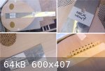
With everything as it should be, the alignment is fixed - in preparation for the sound board to bowl gluing operation - by drilling holes for two
wooden pegs (i.e. toothpicks - just under 2 mm in diameter) positioned at the bottom of the bowl and on the neck. The peg hole at the bottom of the
bowl will eventually be covered by the edge banding and that on the neck by the fingerboard. This is a method sometimes used by the 16th C lute
makers.
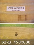
Just so that I don't forget, a makers label has been printed (using non historical Microsoft Word and laser printer!) and glued in a position where it
will be visible through one of the two sound holes.
Additionally, I have marked the end plate of the bowl with my brand - another practice of some of the 16th C lute makers.
I know of one professional guitar maker who goes so far as to ink stamp all of the sound board braces with his mark - helpful, no doubt, in
determining any future unauthorised modifications to his work.
|
|
|
jdowning
Oud Junkie
Posts: 3485
Registered: 8-2-2006
Location: Ontario, Canada
Member Is Offline
Mood: No Mood
|
|
Before gluing the sound board to bowl, both sound board and bowl were 'tap tested' to see if any useful data might be obtained for future
reference.
I was unable to determine anything from tap testing the sound board by following the instructions given by Robert Lundberg in "Historical Lute
Construction". Lundberg's guidance applies to a lute with typical late 16th C/ early 17th C bracing (treble and bass bar below a bridge designed for
more than seven courses) so this may be the reason?
However, Lundberg does admit that his method offered is not definitive and does little to detail the actual procedures that he uses.
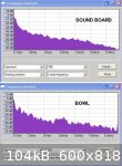
In an effort to obtain some measurable data for future reference and comparison, the sound board and bowl were each 'tap tested' and the sound
recorded with a Zoom H2 digital recorder. The sound files were then analysed (using 'Audacity software).
The sound board was tapped at the centre of the bridge and the bowl, on the side, at its widest point.
The attached images show the spectrum analysis results. What do they all mean with respect to a completed instrument? I have no idea at this point in
time!
|
|
|
jdowning
Oud Junkie
Posts: 3485
Registered: 8-2-2006
Location: Ontario, Canada
Member Is Offline
Mood: No Mood
|
|
A quantity of hide glue will be allowed soak overnight in preparation for gluing the sound board to bowl tomorrow.
In the meantime, I am considering using for this project - in order to save time and progress the work - a set of lute pegs that I turned from
Brazilian Rosewood some years ago. The design of the pegs is quite plain - lacking the usual decorative groove(s) or, alternatively collar just below
the peg head. So, I thought that it would be interesting to investigate the feasibility of adding a collar to these pegs made from a contrasting
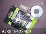
material - in this case wire made from the metal tin.
Tin looks like the precious metal silver but does not quickly tarnish like silver. For this reason, it was often used by early civilisations as a
substitute for silver for decorative metal coatings and inlays.
Tin wire is readily available from most hardware stores in the form of 'Lead Free' solder - now used in place of lead based solders for applications
such as domestic water systems. This material is pure tin except for the addition of a small amount of silver necessary to make the solder flow more
easily. Solid wire solder of this kind is usually 2.5 mm or greater in diameter but rosin cored lead free solder is available in smaller diameter down
to 1.5 mm. The latter material is the solder used for these trials - the larger diameter solid wire being suitable for 'dot' inlays in the end of a
peg head.
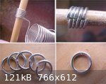
Tin wire solder is quite soft and easily cut with a sharp knife and formed by hand. To make a peg collar, the wire is first wrapped around a wooden
dowel of suitable diameter - like a spring - and then cut with a fine razor saw to make the rings (an old jewelers trick). The diameter of the
individual rings may be further reduced by cutting a little material from the gap and then reshaping the ring on a tapered mandrel (I use the handle
of an artists paint brush)
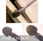
The peg is prepared for accepting the collar (ring) by filing a groove just below the peg head with a small triangular file.
During this operation, the peg is held, for convenience, in a peg shaper (with the blade removed).
Once the ring diameter has been adjusted to the correct size, the collar may be permanently glued in place with epoxy cement.
The method works but my wife - as an independent critic - is not impressed with the result. So, whether or not it will be used for this project
remains to be seen!
Out of interest, the assembled oud components have been individually weighed and total weight of bowl, soundboard, peg box and pegs is about 600
grams. The fingerboard, inlays and varnish are not expected add more than an additional 50 grams in total - so this is within target weight
expectations.
CORRECTION! the 1.5 mm lead free wire solder used here is not flux cored (although the packaging says that it is) but is a solid wire alloy of 96%
pure tin and 4% silver. This product is from the Bernzomatic 'Speciality Solder Kit SSWS 100'.
|
|
|
jdowning
Oud Junkie
Posts: 3485
Registered: 8-2-2006
Location: Ontario, Canada
Member Is Offline
Mood: No Mood
|
|
The sound board has been glued to the bowl and is being left overnight for the glue to fully dry.
Using hot hide glue, the edges of the bowl and ends of the braces were first coated with glue. Next the neck block face was coated with glue and the
sound board (correctly centred with the alignment pins) was clamped to the neck block with tape and a cork lined caul held in place with elastic bands
to provide pressure to the centre area of the joint. Working around the edge of the sound board - bit by bit - hot glue was worked into the joint
surfaces with a thin spatula, the gelled glue liquified with a hot iron and the joint taped in place. At each bar end positions the glue joint was
heated with the hot iron applied to the side rib and side pressure applied with a small block of wood taped in place.
With the sound board completely glued and taped, the caul at the neck block was removed and the edges of the joint in that location were reheated and
re-taped to ensure a tight joint.
Tomorrow the tape will be removed and the sound board trimmed and finished to size around the edge of the bowl.
|
|
|
SamirCanada
Moderator
Posts: 3404
Registered: 6-4-2004
Member Is Offline
|
|
very nice john!
this is really starting to near completion!
so are you going to be using your newly designed half binding tool??
|
|
|
jdowning
Oud Junkie
Posts: 3485
Registered: 8-2-2006
Location: Ontario, Canada
Member Is Offline
Mood: No Mood
|
|
Yes, I shall be using the half-binding tool Samir (not the Lee Valley mini rebate plane adaption) but only for the sound board edging as I shall cut
the rebate for the banding on straight sides of the fingerboard on a router for convenience. This means that the fingerboard must be prepared prior to
gluing to the neck.
I have decided to use boxwood for the fingerboard as this is very hard and close grained (unlike the more open grained Ebony) and - 'off the plane'
has a mirror finish. It is a quite a resonant wood too - so might be a good (but costly) choice as keys for an xylophone.
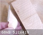
I have two seasoned logs of 30 year old Persian boxwood as well as a quantity of very old boxwood like material in small billets. I was told that this
was 'South American boxwood' by the seller, when I bought it over 30 years ago, but he likely did not know exactly what the species was. However, it
is very similar in colour, texture and hardness to the Persian boxwood as well as being more consistent in straightness of grain - as can be seen from
the attached image (Persian boxwood sample above the 'S.A. boxwood' sample). Note that the core of the Persian boxwood is significantly offset to one
side of the log so the wood is potentially unstable Reaction (or Compression - not sure which) wood. This means that this particular piece may be less
suitable for fingerboard material - although, given the thinness of the fingerboard - this likely would not be too significant once glued to the more
stable Spruce neck.
The fingerboard will not extend from the nut to the neck joint - as appears to be common practice on modern ouds. Following standard procedure for
lutes of the 16th/17th C (which may also have reflected earlier oud practice - judging from the old Persian miniature paintings) the sound board will
overlap the neck joint providing additional strength and reinforcement to the joint.
|
|
|
jdowning
Oud Junkie
Posts: 3485
Registered: 8-2-2006
Location: Ontario, Canada
Member Is Offline
Mood: No Mood
|
|
I have used 'standard' masking tape for clamping the sound board during the gluing operation - strong enough without the risk of grain 'pull out' when
the tape is removed. To minimised this risk, the tape is pulled back on itself at an angle to the wood grain. I should mention that the overhanging
edges of the sound board should be rounded off slightly - prior to the gluing operation - to avoid tearing the tape as tension is applied.
The sound board overlap has been trimmed using a sharp chisel followed by a file and curved scraper. Removal of the surplus surface glue enables
inspection of the sound board to bowl joint. As a result, a small section (about 5cm long) just below the neck block was found to be unglued so this
will be corrected by inserting the spatula into the joint with hot glue, melting the glue in the joint with the hot iron and then re-taping. I am not
completely satisfied with the perfection of joint at some of the brace locations but will leave well alone as attempting to reheat the glue with a hot
iron to 'improve' matters may weaken the glue (as it is not possible to re-moisten the bar ends).
The sound board has a dip in the centre measuring about
2 mm. The sound board was braced when relative humidity was about 55% so the curvature (from the original flat) is likely due to a combination of
shrinkage of the hide glue and the sound board wood across the grain at the current RH of around 45%.
Given this situation, no additional 'dip' was deemed necessary by profiling the sides of the bowl. Lets see how it works out in practice!
|
|
|
jdowning
Oud Junkie
Posts: 3485
Registered: 8-2-2006
Location: Ontario, Canada
Member Is Offline
Mood: No Mood
|
|
The small section of 'dry' joint on the sound board/bowl glue line has been repaired by introducing water into the joint with a thin spatula dipped in
hot water. Hot hide glue was then worked in with the spatula, heated with a hot iron, the sound board edge taped down and left for the glue to fully
harden.
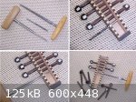
Having decided to use Rosewood lute pegs for this project, the pegs have been fitted to the peg box. This is more conveniently done before gluing the
peg box to neck.
I use three tools for this job - the wood drill used to make the pilot holes, a 1:25 taper reamer (made from a standard Morse taper reamer reground to
specification by a local tool maker) and a standard 1:30 taper violin peg reamer.
The pilot holes were drilled in the peg box sides before assembling the peg box. so the alignment of each peg hole was first verified using the pilot
drill. Three holes were found to be slightly out of alignment - the remainder being pretty well 'spot on'. The misalignment was corrected by applying
side pressure to each reamer as the hole was being cut.
All the pegs are numbered in sequence so that they may be correctly located for final assembly.
As the pegs have been recovered from an earlier lute project, the string holes are already drilled.
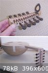
The completed pegbox assembly has been 'dry fitted' to the oud to check proportions. The peg box is more compact than that of a modern oud (overall
length being about equal to bowl depth) - hence the need for (lute like) closer spaced pegs with relatively small peg heads.
Next to make the fingerboard.
|
|
|
jdowning
Oud Junkie
Posts: 3485
Registered: 8-2-2006
Location: Ontario, Canada
Member Is Offline
Mood: No Mood
|
|
The section of sound board overlapping the neck joint has been inlaid with ebony banding to the full sound board thickness at this location (just
under 2 mm). This is for convenience and appearance in blending the sound board edge banding and the fingerboard banding.
The boxwood fingerboard has been planed oversize to about 4 mm maximum thickness so that when finished will taper in thickness from the nut down to 2
mm at the neck joint end. The blank has also been cut to the correct taper of the neck but has been made longer than necessary to allow for final
fitting and adjustment to length.
A 4 mm wide rebate for the banding has been cut (for convenience) on a router table. As the boxwood is very hard and brittle, very light depth cuts
were necessary to prevent chipping the sides of the blank. About 0.8 mm of material has been left underneath the rebate so that the fingerboard can be
fully assembled, trimmed and adjusted in thickness and taper - for correct action - before gluing it to the neck.
The Persian boxwood/Ebony tiles for the edge banding will be made in the same way as the banding for the bridge and peg box (see page 7) so there is
no need to repeat the procedure here. The only difference is that the banding for the fingerboard will be made thicker (about 3.5 mm thick).
|
|
|
jdowning
Oud Junkie
Posts: 3485
Registered: 8-2-2006
Location: Ontario, Canada
Member Is Offline
Mood: No Mood
|
|
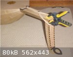
The peg box has been completed by gluing the finial in place and filing it to blend in with the peg box contours.
To glue the peg box to the neck I have used a hot hide glue with a higher 'bloom strength' than the hide glue used for building and assembling the
bowl and sound board. This stronger glue is faster setting so can be used for uncomplicated joints.
Several 'dry' test runs were made to determine the quickest method of clamping the peg box to the neck. In this case I have employed an improvised
combination of a spring clamp together with elastic bands using a couple of screws providing temporary anchor points in the neck. (the screw holes
will, of course, eventually be hidden by the fingerboard.
The material under the oud is a 'non-slip' rubber carpet underlay to facilitate handling of the oud on the slick kitchen counter top next to the stove
and glue pot.
This week end might be an appropriate time to order unbleached bone for the nut and gut for the frets - I need replacement fret-gut for my lutes
anyway as the stuff does not last forever.
The gut frets will be double tied (rather than being a single gut strand often used by many modern lutenists, myself included - a cost consideration
as fret gut is quite expensive) this being generally the way early lute frets were tied and the oud engraving seems also to represent double strand
frets. Greater cost unfortunately but a double strand fret should last longer (i.e.wear better).
In order to keep the string 'action' above the frets as low as possible I shall likely use graduated frets that reduce in diameter from nut to
soundboard.
|
|
|
jdowning
Oud Junkie
Posts: 3485
Registered: 8-2-2006
Location: Ontario, Canada
Member Is Offline
Mood: No Mood
|
|
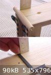
With the peg box now glued in place, it is possible to make a preliminary estimate of the string action in order to finalise the finger board
taper.
With a wooden dowel in the position of the nut and a nylon string connected to the bridge, measurements of string clearance at the neck joint and nut
can be determined. The string clearance at the neck joint on the treble side measures between 2.5 and
3 mm. However, about 1 mm of the original neck 'set back' at the nut seems to have been 'lost' since assembly of the sound board to the bowl.
Before finally establishing the measured finger board taper from nut to neck joint, the oud has been moved away from the heated kitchen (at 45 to 50%
Relative Humidity) to a cooler part of the house to stabilise for a few days at a higher - more normal year round - relative humidity level (60 to 65%
RH). This may result in a recovery of the original neck set back as the wood of the oud expands slightly.
In the meantime work on assembling the fingerboard and banding can proceed on the assumption that a maximum thickness of 4 mm for the finger board
will be adequate to provide the required taper.
|
|
|
| Pages:
1
..
10
11
12
13
14
..
16 |


