| Pages:
1
..
3
4
5
6
7
..
16 |
Peyman
Oud Junkie

Posts: 496
Registered: 7-22-2005
Member Is Offline
Mood: Mahoor
|
|
I found another picture. Couldn't find out where it was from but looks like a fresco. Just for the sake of completion.
|
|
|
jdowning
Oud Junkie
Posts: 3485
Registered: 8-2-2006
Location: Ontario, Canada
Member Is Offline
Mood: No Mood
|
|
Peyman - could you please edit the size of your image to 800 pixels or less (horizontally) so that the image does not go "off screen" on my PC - it
makes it a lot easier for me to work on the thread? The higher resolution should not be necessary for clarity.Thanks.
So - Persian (?), oud like, sickle shaped pegbox, frets(!), no sound holes(?), five pegs (equivalent to 5 courses in the mind of the artist?). Also,
again, the 'strange' heavily decorated sound board and sloping profile from neck to bowl - implying a carved bowl (but not necessarily so). All from a
period much earlier than the 13th/ 14th C oud of this project, of course.
Interesting how the tambourine - instantly recognisable and popular even today as a percussion instrument in the West - has remained unchanged over
the centuries and across musical cultures.
|
|
|
Peyman
Oud Junkie
Posts: 496
Registered: 7-22-2005
Member Is Offline
Mood: Mahoor
|
|
Ok, I fixed it.
You can see the slope in some Persian plucked instruments, setars come to mind. Also, the soundboard with "wings" and the "beard" is still used in
some instruments like the baglama and some Greek instruments as well.
The small soundholes look like what they use on setars today, where they are arranged in a floral design.
|
|
|
jdowning
Oud Junkie
Posts: 3485
Registered: 8-2-2006
Location: Ontario, Canada
Member Is Offline
Mood: No Mood
|
|
Perfect! Thanks Peyman.
|
|
|
jdowning
Oud Junkie
Posts: 3485
Registered: 8-2-2006
Location: Ontario, Canada
Member Is Offline
Mood: No Mood
|
|
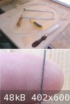
Following the picture posted by Peyman, this is an appropriate moment to consider another design detail - the tuning pegs. As can be seen from this
image, the peg heads appear to circular in profile unlike the violin peg shape often found on ouds today.
The pegs on the oud engraving also seem to have circular peg heads as do the pegs on, for example, on the familiar oud like instrument depicted in the
13th C. Cantigas de Santa Maria. Both of these examples also show the pegs to have long shanks. This way of representing the pegs may, of course, just
be an artistic convention - simply because they are easier to draw that way perhaps.
Nevertheless, the pegs on my old Egyptian oud are circular in profile so this is the style of peg that I will be making for this project but with
somewhat shorter shanks - long shanked pegs being weaker.
The pegs will be made from well seasoned Pear tree wood that I cut into billets for making pegs about 30 years old. The tree was given to me by a
friend and neighbour who thought that I might put the wood to good use. As both he and his wife are - sadly - now deceased, the use of the wood for
this project will be a small memorial to them. I have about 70 billets in stock so there is plenty of choice.
The bridge will also be made from this material.
The wood is very fine grained, working nicely under the plane, so should be good for turning also. I shall measure a sample later to determine the
specific gravity.

|
|
|
jdowning
Oud Junkie
Posts: 3485
Registered: 8-2-2006
Location: Ontario, Canada
Member Is Offline
Mood: No Mood
|
|
Meanwhile - back to the work bench!
On inspection, there is a problem with two of the glued panels. I was unable to work quickly enough in coating the glue joint and positioning the
panels before the glue in the joint started to gel. This prevented the joint surfaces coming tightly together leaving a very slight but visible (and,
therefore, in my judgement, unacceptable) gap in the joint.
The method of gluing the panels has, therefore, been modified to overcome this problem - based on the method generally used for gluing sound board to
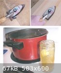
bowl. This involves reheating the glue so that it melts in the joint - using a hot iron - allowing the joint surfaces to come tightly together under
the clamping pressure.
An iron heated over an open flame could be used for this purpose but I am using a small electrically heated, thermostatically controlled, iron for
convenience. These irons may be purchased from hobby shops (used for applying plastic film to model aircraft?) at a reasonable price. They can also be
purchased from luthier supply houses at double the cost.
When the glued joint surfaces are pressed together on the work surface, the hot iron is simply moved over the joint until the gelled glue is seen to
re-melt and the joint fully close. The seam is then clamped to the flat work surface using a straight wooden batten and two 'G' clamps as previously
described.
The setting of the iron thermostat is in the mid position. The iron has a 'Teflon' sole so that any surplus glue will not stick to it.
My glue pot is simply a small, screw top glass jar set in a pan of boiling water to melt the glue. The hot glue is diluted with water to the correct
consistency - running off the glue brush in a steady stream. After use, the jar is sealed and left in a refrigerator for use the following day. This
should be good for about a week after which time it will be thrown away and a fresh batch of glue will be made up.
The good old fashioned cast iron glue pots that can still be seen in some professional luthier workshops (I have a couple myself) are not required for
occasional, small production, work. A glass jar is cleaner, cheaper and holds small measured quantities of glue so is very economical in use.
|
|
|
Edward Powell
Oud Junkie
Posts: 1212
Registered: 1-20-2008
Member Is Offline
Mood: g'oud
|
|
JD
...this is a fascinating thread, and I am really looking forward to the remaining steps.
One question... I noticed that the bridge is REALLY far back... so much so that the behind bridge brace is not even there. I am curious because my
latest oud/sarod combo dbl-neck guitar, I also put the bridge VERY far back - so far that i also had to eliminate this first brace.
I had ALOT of worries about the possible negative outcome for the sound quality. People advised me not to do this- saying that the optimum bridge
placement is as close to the SB center as possible. ---but I NEEDED the bridge REALLY far back for ergonomic reasons.
How do you think the sound is affected with the bridge so far back??
|
|
|
jdowning
Oud Junkie
Posts: 3485
Registered: 8-2-2006
Location: Ontario, Canada
Member Is Offline
Mood: No Mood
|
|
To follow the complete analysis and arguments that has led to the decision to move ahead this project, you will need to wade through "Analysis of an
Early Oud Woodcut" (Advice, Tips and Questions Forum" and also check out "Below Bridge Bars - a Missing Link?" (Ouds Projects Forum).
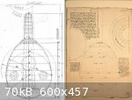
However, in order to briefly summarise the situation I will reference the attached geometrical diagram used to analyse the barring (a speculative
proposal) of the 12thC/13thC engraving of an oud compared to the barring geometry of a lute given by Arnault de Zwolle circa 1450.
The Arnault drawing is 'dual purpose' showing the barring geometry as well as the bulkhead placement of a mold required to build the lute. One
striking feature about this lute is an 'unusually', massive end block below the bridge with no other bars. The oud does not have an end block but a
'lute like' end plate of only a few mm in depthas well as a first bar.
The front edge of the bridge in both the oud engraving and the Arnault lute is 1/6 of the body length which is the classic lute bridge position -
confirmed later in the early 17th C by the great French theoretician Marin Mersenne. (see the reference scale alongside the oud diagram for
comparison) as well as on surviving lutes. Lutes (judging from surviving lutes) did not have a first bar below the bridge but instead had a kind of
fan bracing arrangement with a "bass bar" approximately aligned with the first bar position on an oud. Either way, the objective would seem to be, for
lute or oud, to significantly stiffen the sound board area below the bridge.
Note that the bridge length in the oud engraving is way off scale and will be much shorter (and narrower) than represented as it must carry only 5
double courses. There is, in fact, physically enough space for the first bar below the bridge according to this geometry (the bars shown as dashed
lines in the geometry will be incorporated)
I do not anticipate any problem with this barring arrangement but, of course, will have to build the oud to find out just how it all works - if at
all!
|
|
|
Edward Powell
Oud Junkie
Posts: 1212
Registered: 1-20-2008
Member Is Offline
Mood: g'oud
|
|
So if I understood, you are presenting ample evidence that plenty of ouds/lutes have been built this way in the past - - - but you yourself have not
yet experienced the results?
My experience was very good--- having the bridge so far back and with no first brace worked very well.
It is amazing how in luthiery there always seems to be a glaring exception to every stated "rule"!
|
|
|
jdowning
Oud Junkie
Posts: 3485
Registered: 8-2-2006
Location: Ontario, Canada
Member Is Offline
Mood: No Mood
|
|
Not at all!
I have built copies of surviving lutes with the classic 1/6 bridge placement (including the Arnault lute) as well as lutes with alternative bridge
locations. The European iconography of the 15th C and 16th C shows many examples of bridge placement on lutes at variance with this rule - although it
is risky to depend too much on evidence presented by paintings when attempting to recreate early instruments.
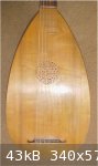
One fragment of an early lute belly survives with clear markings of an original low bridge position. This is from a lute by the renowned maker Laux
Maler - cat. No. M154 in the Nurnburg Germanisches Nationalmuseum. Other bowl fragments by Maler survive in other European museums - providing
sufficient evidence from which to make a replica.
Here is an image of the belly of a successful reconstruction that I made of the Maler lute in 1979. Note the low bridge position.There is no bracing
below the bridge either.
Off topic - so just for general information and interest.
|
|
|
Edward Powell
Oud Junkie
Posts: 1212
Registered: 1-20-2008
Member Is Offline
Mood: g'oud
|
|
HOLY SMOKES!
...but how does this affect the sound?
I mean, for example, if you took exactly this lute, and moved the bridge forward 6cm, and added a behind bridge brace - how would the tonal properties
change? ....more bass? more sustain? less attack??
thanks!
---also, there is really not much AIR ventilation on such a lute... I wonder how this affects the tone also, compared to an oud with 3 holes?
|
|
|
jdowning
Oud Junkie
Posts: 3485
Registered: 8-2-2006
Location: Ontario, Canada
Member Is Offline
Mood: No Mood
|
|
Interesting questions with complex answers that I have had no reason to investigate by comparative experimentation. Perhaps others may have done some
work in this direction but I am not aware of it.
However, your questions are not strictly relevant to this thread which is concerned primarily with recreating an oud based on the 14th C engraving
following the speculative barring geometry proposed in previous threads - including the specified bridge position. Slender evidence to go on perhaps
but unlike the European lute where several examples have survived for study - at least from the early 16th C - nothing tangible survives of the oud
prior to the late 18th C. Sad but true.
There may be scope for some very limited experiments - using the completed instrument as a 'test bed' - in order to investigate the effect of
different numbers of sound holes and barring variations etc. that are within the scope of the specified geometry. However, there are so many potential
variables involved that ensuring exactly comparable conditions will be practically impossible to achieve. Nevertheless, should there be any meaningful
results from such tests they will certainly be posted, for information, but as the subject of a separate thread.
Maybe your best bet would be to start a new topic on the Forum that deals specifically with your questions? I for one would be interested hear about
the experiences, theories and opinions of other members but - please - not on this thread!
|
|
|
jdowning
Oud Junkie
Posts: 3485
Registered: 8-2-2006
Location: Ontario, Canada
Member Is Offline
Mood: No Mood
|
|
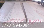
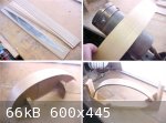
The first of the batch of four panel sound board blanks is glued up, dried and ready to go.
The first step is to level the blank evenly on both sides to remove any slight 'step' at the panel joints. The blank is currently about 2.5 mm to 3 mm
thick. Leveling is done using a cabinet scraper (I do not trust the smoothing plane as it may cause excessive tear out of the grain). The scraper is
worked in all directions across the surface of the blank. To highlight any high spots in the surface, a toothing plane is also used. (The blade on
this kind of plane produces fine scratches on the surface - originally used for preparing the glued surface of panels prior to veneering). The scratch
marks are then removed with the cabinet scraper to produce a smooth finish overall.
The next step will be to cut out the blank to the required profile (cut well oversize by about 12 to 15 mm) prior to final thicknessing to around 1.5
to 2 mm (1 mm thick in the sound hole areas to facilitate cutting in of the rosettes).
|
|
|
jdowning
Oud Junkie
Posts: 3485
Registered: 8-2-2006
Location: Ontario, Canada
Member Is Offline
Mood: No Mood
|
|
In the meantime, work has progressed with preparation of the rib blanks. (It helps to switch between tasks to relieve any work tedium - but not the
most efficient way to go). Two partial rib sets are to be used - alternating each rib of the bowl in sequence and matching grain pattern.
All of the rib blanks have been prepared on one side (the inside face) by planing and final smoothing with a cabinet scraper. The current thickness of
about 2mm is well oversize so will be reduced to about 1.5 mm final thickness by smoothing the outside face with a cabinet scraper.
The rib blanks have been cut oversize to equal length (less material to remove during the final stages of thicknessing).
To ensure that the ribs are used in sequence during assembly of the bowl the ends of each stack of blanks has been marked with red ink.
|
|
|
charlie oud
Oud Junkie
Posts: 694
Registered: 11-19-2007
Location: Newcastle upon tyne. UK
Member Is Offline
Mood: chords prefer frets
|
|
| Quote: | Originally posted by Edward Powell
HOLY SMOKES!
...but how does this affect the sound?
I mean, for example, if you took exactly this lute, and moved the bridge forward 6cm, and added a behind bridge brace - how would the tonal properties
change? ....more bass? more sustain? less attack??
thanks |
 The sound would be 6cm shorter The sound would be 6cm shorter  te he he sorry fellas could'nt resist te he he sorry fellas could'nt resist
|
|
|
jdowning
Oud Junkie
Posts: 3485
Registered: 8-2-2006
Location: Ontario, Canada
Member Is Offline
Mood: No Mood
|
|
Thanks charlie oud - I was wondering!
The second sound board blank was glued up and completed today. The original pair of panels - assembled without using a hot iron to remelt the glue -
are not satisfactory as the glue has not fully penetrated the joint surfaces. They have, therefore, been taken apart by first wiping the joints with a
damp rag and then using the hot iron to melt the glue and separate the joint surfaces. Another big advantage of using hot hide glue - it is easily
reversible. The panels have now been re-jointed in preparation for making sound board blank #3.
This batch of glue has been in use for a week so has now been discarded and a fresh batch made up. Before throwing it out, the heated glue was diluted
with hot water to the consistency of a thin varnish and brushed over the neck block surface. This 'glue size' is to seal the grain of the neck block
preventing the end grain of the wood from absorbing too much glue during assemby of the ribs to the neck block (which could result in a weakened
joint).
The second neck block is from another project (see 'Old Project - New Lute' on the Forum). Thought that I would use the opportunity to 'size' that at
the same time.
|
|
|
jdowning
Oud Junkie
Posts: 3485
Registered: 8-2-2006
Location: Ontario, Canada
Member Is Offline
Mood: No Mood
|
|
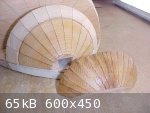
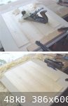
The first of the sound board blanks to be completed has now been smoothed on both sides to remove any surface glue and reveal the grain figuring and
any faults. A pattern of half the sound board profile - cut from thick card - is used to determine the best part of the blank for the finished
soundboard.
The blank will be cut to the required profile - oversize by about 12 mm - for trimming later. A good method to use for marking out an oversized
profile is the old trick of using a metal washer - rolled around the outside edge of the card pattern, like a wheel - with a pencil held in the centre
to trace the profile. (This style of washer - with the relatively small centre hole - was obtained from a local auto parts dealer).
As four (or five) sound board blanks are being prepared, the best of the bunch will be selected and the rest then kept in stock (untrimmed) for future
projects.
|
|
|
jdowning
Oud Junkie
Posts: 3485
Registered: 8-2-2006
Location: Ontario, Canada
Member Is Offline
Mood: No Mood
|
|
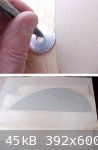
For sound board blank #4, the method has been modified slightly to improve the procedure for gluing the joints. This is the final blank of this
batch.
By the time both edges of the joint have been coated with hot glue and pressed in place (under pressure), the glue has gelled sufficiently to prevent
the joint faces coming fully together. The glue must, therefore, be remelted with a hot iron. This time - instead of applying the hot iron directly to
the joint - a strip of cooking paper was first laid over the joint followed by the iron. This procedure is less messy and works well.
After the joint surfaces have moved into position they are held in place, flat on the work surface - as before - with a wooden batten clamped over the
joint.
The cooking paper is 'Baker's Mate non stick parchment paper'. It is for use in the oven or microwave - 'greaseproof', waterproof, temperature
resistant to 215 C (420 F), strong and reusable. Good stuff for this application.
There are likely other similar brands available on the market. Do not used waxed paper!
|
|
|
Edward Powell
Oud Junkie
Posts: 1212
Registered: 1-20-2008
Member Is Offline
Mood: g'oud
|
|
The precision of your work is REALLY inspiring.
I am going to use some of your methods the next time I make an oud -
Thanks for sharing all of this!

|
|
|
jdowning
Oud Junkie
Posts: 3485
Registered: 8-2-2006
Location: Ontario, Canada
Member Is Offline
Mood: No Mood
|
|
Thanks!
|
|
|
jdowning
Oud Junkie
Posts: 3485
Registered: 8-2-2006
Location: Ontario, Canada
Member Is Offline
Mood: No Mood
|
|
The rib blanks have now been planed and finished to a thickness of about 1.5 mm with a cabinet scraper. Using the rib template to evaluate the best
part of the rib blanks, the rib centre position has been marked on each blank for reference during bending.
Nothing special about the hot bending technique - just using a heavy duty propane heated bending iron - dry heat no moisture. (Note - I do not use a
kind of special single handed technique - one hand must hold the camera!). The modified jig is used as a guide to the correct rib profile. The rib
centre mark is used as a reference to ensure matching grain pattern between ribs.
Each completed hot bent rib blank has been set in a simply made carrier to maintain the rib profile and reduce any spring back. Each rib will
eventually have to go back on the bending iron for adjustment to the correct profile prior to fitting and gluing.
|
|
|
jdowning
Oud Junkie
Posts: 3485
Registered: 8-2-2006
Location: Ontario, Canada
Member Is Offline
Mood: No Mood
|
|
All of the rib blanks have now been hot bent to the required profile.
So, for a change of pace, work on the selected #4 sound board blank has started. Both surfaces must first be planed level - a preliminary operation
prior to final thicknessing. To avoid tear out of the grain, the blade of the smoothing plane has been freshly sharpened and set for the finest cut
possible. The plane is worked in all directions - crisscrossing diagonally across the grain - until all high spots and surface glue have been removed.
The plane marks still remaining will be removed during the final finishing stages. The rough finished sound board blank is now just over 2 mm in
thickness.
The sound board profile has been marked oversize and will be cut out on a bandsaw ready for the final finishing process.
|
|
|
jdowning
Oud Junkie
Posts: 3485
Registered: 8-2-2006
Location: Ontario, Canada
Member Is Offline
Mood: No Mood
|
|
Although the soundboard is cut well oversize it was decided not to use the bandsaw to avoid any risk of tearing and splintering of the edges - easily
done when cutting Spruce across the grain with a coarse saw blade.
Instead, the soundboard was cut out by hand - first using a razor saw to trim off most of the waste material. The profile was then scored along the
marked pencil line with several light passes of a sharp craft knife - working with the grain direction - to about a millimeter or so depth of cut. The
final cut was made using a very fine jeweler's saw blade mounted in a fretsaw frame - sawing along the knife cut. This operation was fairly quickly
and successfully accomplished without any splintering. No need for expensive power tools!
Jeweler's saw blades are graded according to fineness of cut, in a range of 20 sizes, from 8/0 the finest to 14. Not sure about the size of this blade
(probably about 4/0) but the teeth are so small that they can only be seen with a magnifying glass.
The sound board surfaces were then inspected and the 'best' side chosen for outside face of the sound board. This face was finished using a cabinet
scraper until flat and smooth. The surface was checked as work progressed by feeling for high spots and irregularities and by eye - looking across the
surface at a low angle under incident light. Human touch can be a very sensitive means of detecting surface variations (of about 0.001 inch or 0.025
mm).
This face will now be left untouched and the final thicknessing will be achieved by removing material from the other side (the underside) of the
soundboard.
|
|
|
Edward Powell
Oud Junkie
Posts: 1212
Registered: 1-20-2008
Member Is Offline
Mood: g'oud
|
|

|
|
|
jdowning
Oud Junkie
Posts: 3485
Registered: 8-2-2006
Location: Ontario, Canada
Member Is Offline
Mood: No Mood
|
|
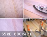
The 'underside' of the sound board will first be made flat and smooth with scrapers and of uniform thickness all over - target 2mm thick initially.
This will then be gradually reduced in thickness according to how stiff the sound board feels as work proceeds.
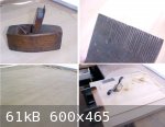
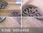
At this stage the toothing plane will not be used for levelling although here, for information, is an example of the underside of the sound board of
an old Egyptian oud - left 'as is' after using a toothing plane. Who says that the underside of an oud sound board should be made silky smooth?!
What was the intention of the luthier here? To produce a better gluing surface for the braces? Or, perhaps, a subtle refinement modifying the sound
board to be more flexible across its width - presumably with acoustical benefits? Or did he just make a mistake and remove too much material with the
toothing plane and let it go at that?
Anyway, the sound board underside on this project will be finished smooth and uniform - at least for first time around!
(For those who may be wondering, the restoration of the Egyptian oud, subject of the attached images, is still pending and will resurface on the Forum
at a later date)
|
|
|
| Pages:
1
..
3
4
5
6
7
..
16 |


