| Pages:
1
..
5
6
7
8
9
..
16 |
Peyman
Oud Junkie

Posts: 496
Registered: 7-22-2005
Member Is Offline
Mood: Mahoor
|
|
No Alami, for the next oud John will carve the body  ) )
John's patience and discussion of details is amazing. This is a really neat project.
|
|
|
jdowning
Oud Junkie
Posts: 3485
Registered: 8-2-2006
Location: Ontario, Canada
Member Is Offline
Mood: No Mood
|
|
Thanks for your kind words and encouragement ALAMI and Peyman. Carved bowls? Not sure about that - although everything is possible.
I have made one carved instrument - having built a replica of an ancient wire strung Irish harp or 'clarsach' as a research project and for an
exhibition at the Canadian Museum of Civilisation some years ago. These fascinating instruments were traditionally constructed from three main parts -
sound box, harmonic curve and front pillar - each carved from the solid (decorated with burnt engraved work), joined together with precise, specially
shaped mortice and tenon joints. No glue was used in the construction of these ancient instruments, the whole structure of a harp being locked firmly
together by (the considerable) string tension alone.
But that's another story - sorry for the diversion!!
|
|
|
jdowning
Oud Junkie
Posts: 3485
Registered: 8-2-2006
Location: Ontario, Canada
Member Is Offline
Mood: No Mood
|
|
Still too wet and humid to do instrument assembly work (and busy with other non-instrument making priority activities). However, component
preparation and fabrication can go ahead - as time permits.
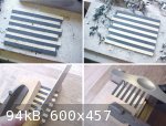
The hot bent rib blanks have now been sorted into their proper sequence for assembly in the bowl and numbered accordingly. The bowl mold has also been
numbered to match the rib positions. The rib centre lines were marked on the ribs prior to bending and are now used as a reference for marking the rib
profiles. The previously made metal rib template is clamped to each blank - with centre lines aligned - and the rib outline traced in pencil. The rib
profile marking is only an approximate guide for rough trimming of the rib blanks that are next to be cut and left slightly oversize.
|
|
|
jdowning
Oud Junkie
Posts: 3485
Registered: 8-2-2006
Location: Ontario, Canada
Member Is Offline
Mood: No Mood
|
|
Conditions have been improving with dry Spring conditions so a 'window of opportunity' for gluing operations presents itself.
Today the temperature is 25 C, sunshine, with a strong breeze blowing. A beautiful late Spring day - tempted to just sit out side and relax but -
removed the Winter shutters from my small workshop (temporary conversion from a tinsmith workshop) to allow air to freely circulate. The relative
humidity dropped dramatically from 65% to 50% during the morning so decided to go ahead and glue the rosette bracings.
Using the kitchen for gluing operations has been very inconvenient (not to mention justified complaints from my wife who keeps reminding me - in vain
- that her kitchen should not be used as a workshop extension or laboratory for luthier experiments). So a low cost, portable, electric two ring
cooking range has been purchased to heat the glue pot.
The concern is that in the confined space of the workshop, the steam from the water jacket heating the glue pot will raise the relative humidity of
the work space.
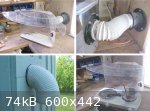
My tinsmith operations (involving a lot of soft soldering with toxic fluxes) have necessitated installation of a fume extraction hood - using a high
capacity fan to extract the fumes to outside the workshop.
This is a home built unit. The hood is made from 3mm 'Plexiglas" (or Acrylic) plastic sheet formed by softening the plastic with a hot air gun and
then bending it to shape. - all glued together with epoxy glue. The compact, high output fan is a plastic 6 inch (150 mm) diameter purchased as
surplus stock (ex computer? - from the days when computers occupied whole buildings!). The fan unit has been installed inside a box in the wall of the
workshop - venting to the outside via a standard 6 inch stove pipe bend (fitted in a wooden block so that it can be rotated if necessary, dependent
upon wind conditions). The connections between the hood and fan are made from standard black plastic sewer pipe fittings - with a piece of flexible,
'laundry drier' tubing connected with hose clips.
This arrangement has worked very well as a soldering station for a decade or so. Testing it with the boiling glue pot confirmed that the steam was
effectively removed to outside the building - perfect!
|
|
|
jdowning
Oud Junkie
Posts: 3485
Registered: 8-2-2006
Location: Ontario, Canada
Member Is Offline
Mood: No Mood
|
|
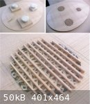
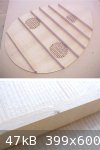
With the workshop glue station up and running, the rosette bracing was installed. The purpose of the bracing is to support the delicate tracery of the
rosette against damage and to stiffen the area of the sound hole. The bracing is made from spruce scraps from sound board material - about 1.5 mm
thick by about 3 mm deep.
The gluing operation was carried out in a rotating sequence. One brace was coated in glue and held in place for a few seconds - until the glue gelled
- and then clamped flat with a weighted caul before moving on to the next rosette.
The completed bracing will be left for a day until the glue has cured hard. The bracing will then be planed to a uniform height (which will, in turn,
help test the strength of the glued joints) before moving on to the next step.
If the relative humidity conditions remain favourable, the sound board braces will next be glued in place.
|
|
|
jdowning
Oud Junkie
Posts: 3485
Registered: 8-2-2006
Location: Ontario, Canada
Member Is Offline
Mood: No Mood
|
|
Low humidity again today so went ahead with gluing the soundboard bracing.
The rosette bracing has been planed (in situ) to a uniform depth of about 2.5 mm.
As the gluing of the braces has been delayed for a while - after the unsuccessful attempt previously posted - the brace positions on the sound board
were lightly sanded to remove any oxidation that might affect the glue bond. These surfaces and the joint surfaces of the braces were also cleaned
with a cloth moistened in propyl alcohol - just for good measure.
The go-bar rig was again used but the Ash go-bars have been modified to reduce the loadings that seemed to be excessive. This was done by reducing
the width of each go-bar from 20 mm to 10 mm - except for the top 50 mm which was left at 20 mm width to preserve correct alignment of each bar under
load. Go-bar thickness remained at about 4 mm.
It was decided to glue only three braces today (for convenience and to minimise the total load on the go-bar rig) - the remaining three will be glued
tomorrow - although with freezing temperatures in the forecast, the workshop heater may need to be turned on. We are not out of Winter yet!
This time around, the go-bar system worked a lot better with no tendency to 'tip over' the narrow, relatively deep braces.
The glue was made a bit thinner - nevertheless, it was still necessary to work quickly to get the braces in position and clamp each one in place with
three go-bars before the glue 'gelled'.
|
|
|
jdowning
Oud Junkie
Posts: 3485
Registered: 8-2-2006
Location: Ontario, Canada
Member Is Offline
Mood: No Mood
|
|
Another dry day yesterday so with the workshop relative humidity maintained between 50% and 55% the gluing of the braces was completed. Maintenance of
relative humidity at these levels is important because once the bars have been glued in place, the sound board is no longer free to expand and
contract across its width with humidity changes.
Today is a different story with rain in the forecast for the next three days.
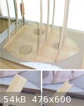
After drying overnight, the sound board was removed from the go-bar rig and then hung on a peg in another room of the house for safe keeping and for
further drying/curing of the glue. At this stage, all of the bars are of equal height of 15 mm. No further work will be done on the sound board until
it is fitted to the bowl.
The pressure of the go-bar clamps causes small indentations in the top of the braces. The braces have been made slightly oversize so these marks will
be planed out later when the bracing is finally finished (after the sound board has been fitted to the bowl).
|
|
|
jdowning
Oud Junkie
Posts: 3485
Registered: 8-2-2006
Location: Ontario, Canada
Member Is Offline
Mood: No Mood
|
|
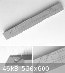
With higher humidity levels a start was made today on another component - the bridge.
Three pieces of pear wood were selected from stock and tested for suitability by hand planing the sawn surfaces to reveal any small defects or grain
irregularities. One piece was found to be suitable with no grain 'tear out' when planed. The wood is close grained and works nicely under the plane.
It has a slight pink colouration with some slight 'fiddle back' grain figure in evidence.
The bridge of the oud in the engraving is very lute like in appearance so the design will follow lute bridge design found on surviving lutes of the
16th/17th C. Comparing the bridge dimensions of my old Arabic oud with those of lutes - the relative dimensions of string spacing and height are
almost identical (the oud string height is a bit higher). The bridge on the Arabian oud is wider than found in lute bridges (that are narrower and
longer) but the 'foot print' (area covered by each) is practically identical.
The extra length on a lute bridge is provided by the carved, 'decorative' ends of the bridge. Here an early 17th C bridge end design has been modified
slightly in order to conform more closely to the oud engraving. This bridge will also have tiled inlays on the front and rear top edges - as depicted
in the oud engraving.
Proportionally this design fits quite well with the bridge shown in the engraving.
|
|
|
patheslip
Oud Junkie
Posts: 160
Registered: 5-24-2008
Location: Welsh Marches
Member Is Offline
Mood: smooth
|
|
Great work,
though I'm glad I'm not in Canada from your description of the weather. Here in the english West Midlands my potatoes are in flower, I've eaten my
first peas from the garden, and summer is coming in with a soft comfortable warmth. The suns just setting at half past nine in the evening after
another lovely day.
Still I couldn't make an oud to save my life.
|
|
|
jdowning
Oud Junkie
Posts: 3485
Registered: 8-2-2006
Location: Ontario, Canada
Member Is Offline
Mood: No Mood
|
|
Here the trees are almost in full leaf although we had a heavy frost in some localities the other day - which is a bit unusual for this part of
Canada. So no spuds or peas here for a while - although dandelions and 'noxious' weeds are pretty well 'ahead of the game' as usual. However, the
growing season although relatively short can be pretty intensive - with vigorous growth of plants and vegetables due to the summer heat and high
humidity levels.
Great if you are a gardener or farmer but not so good for instrument making without some kind of climate control.
|
|
|
patheslip
Oud Junkie
Posts: 160
Registered: 5-24-2008
Location: Welsh Marches
Member Is Offline
Mood: smooth
|
|
It's easy to forget that most people in Canada are south of most people in the British Isles, nearer level with France. And you get summers more like
those in the Dordogne than English ones: hot and sweaty. There again your winters are something else. Brrrrr!
Perhaps you could rig up a solar powered dehumidifier for your workshop.
|
|
|
jdowning
Oud Junkie
Posts: 3485
Registered: 8-2-2006
Location: Ontario, Canada
Member Is Offline
Mood: No Mood
|
|
Small portable dehumidifiers- more than adequate for a small workshop space cost around $200 - they are just little electric powered refrigerators
with an air circulating fan and control unit. It would be nice to have but we usually manage to keep cool by opening windows and using fans. The
advantage of the cold winters and heated building interiors is that the resultant relative humidity can be good for instrument building. Then we use
humidifiers if the air gets too dry (we have one of those)!
Wet, warm and humid today - condensation on cold surfaces - so continued with work on the bridge. The first step is to rough shape the blank and drill
the holes with everything 'square'. As the oud is fretted I am following lute practice with string holes lower on the treble side than on the bass (a
1 mm slope). The drilled and slotted bridge ends are first roughly carved with a chisel to remove excess waste material and then brought close to the
finished contours (I used a small drum sander in a drill press for convenience).
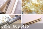
The top front and rear edges of the bridge will have a tiled inlay - matching the sound board edge inlay (yet to be done). This could be applied as a
veneer panel glued to the top of the bridge but I have decided to set the inlay into rebates. The rebates were cut - 1mm deep and 3 mm wide - on a
router table (for convenience again). The sound board edge tiles will be 4 mm wide by about 0.6 mm deep.
The tiled inlay must be glued in place before the bridge can be finished so the next stage is to make the inlay.
|
|
|
jdowning
Oud Junkie
Posts: 3485
Registered: 8-2-2006
Location: Ontario, Canada
Member Is Offline
Mood: No Mood
|
|
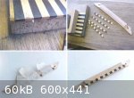
I shall be using African ebony and Persian boxwood for the tiles - both appropriate materials for an early oud.
I purchased two logs of the boxwood from a timber importer in Liverpool, U.K., during the 1970's (he had a huge pile of the logs in a bin - as well as
logs of Indian rosewood, billets of Brazilian rosewood etc. , all sold by weight. Those were the days!) Boxwood is notorious for the length of time it
takes to season but this should be OK for this application. This stuff is hard, close grained and is an attractive lemon yellow colour that should
contrast well with the ebony. It finishes with a mirror surface straight off the plane - nice wood.
The first step is to prepare a few short sticks of the ebony and boxwood - all 5 mm wide and about 2 mm thick. The edges of each strip were trued -
square and straight - on a 'mini' shooting board - ready for gluing.
|
|
|
jdowning
Oud Junkie
Posts: 3485
Registered: 8-2-2006
Location: Ontario, Canada
Member Is Offline
Mood: No Mood
|
|
The Ebony/Boxwood strips have been glued together side by side and both faces of the assembly planed flat and to a uniform thickness of just under 2
mm. During planing, the assembly was held in place on a flat board using double sided adhesive tape.
The inlay strips are made well oversize - about 4 mm wide - to allow for trimming. A line is first scored with a knife as a guide for a fine tooth
razor saw. The work must be firmly clamped during sawing to prevent breakage of the strips.
After each strip has been cut the edge of the assembly is made square and straight by 'shooting' with a plane - ready for cutting the next strip. The
straight face of the strip will be glued into the rebate of the bridge.
Both Boxwood and ebony are brittle woods so some slight tear out or chipping of the edges is hard to avoid. However, as the inlay strips are made well
oversize these flaws will be remove when the bridge is finished to size.
To ensure a close fit in the rebate, the inside corner of each strip has been rounded slightly.
The inlays have now been glued to the bridge and the glue left to fully cure overnight.
|
|
|
jdowning
Oud Junkie
Posts: 3485
Registered: 8-2-2006
Location: Ontario, Canada
Member Is Offline
Mood: No Mood
|
|
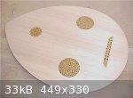
Work on the bridge is now complete apart from final smoothing and finishing.
The black and yellow tile inlay made a dramatic contrast against the pale wood of the bridge so the bridge has been given a primer coat of orange
shellac as a test to see how it looks (and to seal the wood grain). However, I am not sure that I like the overall orange tint of the bridge so may
remove the shellac during final finishing.
The sound hole rosettes have also been coated with orange shellac to penetrate, consolidate and strengthen the thin wood (shellac makes a good glue).
The rosettes will be left with the shellac finish - contrasting with the unvarnished sound board wood.
The bridge has been placed (not glued!) in its correct position on the unfinished sound board just to see how it looks. Note that the sound board, at
this stage, is about 12 mm oversize all round.

|
|
|
jdowning
Oud Junkie
Posts: 3485
Registered: 8-2-2006
Location: Ontario, Canada
Member Is Offline
Mood: No Mood
|
|
Relative humidity is still on the high side but a start was made on the bowl today - hoping that conditions will improve over the next few days.
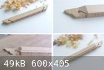
The rib blanks have all been pre-bent, numbered in sequence and left in a drying rack - as reported in a previous post. As there is some 'spring back'
of the pre-bent ribs, each rib blank must first be slightly adjusted again to the exact profile using the hot bending iron
The profile of rib #1, the central rib, has been marked on the blank - in pencil - using the metal rib template.
One side of the blank is carved close to the line (to about 2 mm) using a sharp knife - working in two directions from the centre point of the rib,
following the grain of the wood. Then, using a small block plane, held in one hand, the remaining excess material is cut away down close to the pencil
line.
The accuracy of the joint is tested as work proceeds by placing the rib on a surface plate and viewing the rib against the light to view any high or
low spots. This is quite a severe test but work must continue until no light can be seen along the length of the rib joint. This method works because
the bowl of this oud is semicircular in cross section and the ribs (theoretically) are of equal geometry.
The finished joint surface could be cut using the hand held block plane alone but it is perhaps a bit easier to make the final cuts on either an
inverted jointer plane or on a flat sanding board. I prefer to use a sanding board as I can get the joint very close using just the block plane used
freehand. It is then just a matter of a few light 'swipes' on the sanding board to remove any slight high spots.
The problems with using a jointer plane is that there is only a relatively small surface area to work with, often the plane surfaces are not flat
(poor manufacture) and the rib must be worked in two directions - with the grain of the wood. However, it is all a matter of personal preference and
what works best for each luthier.
Once a perfect joint surface had been obtained on one side the process is repeated for the other joint face.
My sanding board is made from two pieces of 20 mm thick MDF (Medium Density Fibre board) glued together to make a flat surface on which sheets of 220
grit Garnet paper (sandpaper) have been glued.
My surface plate is made from a piece of 8 mm thick plate glass mirror. The mirror - which had lost half of its 'silvering' - was given to me by a
friend ('waste not want not' - this stuff is heavy and expensive when purchased new). A section that still retained its silvering was cut to size
using a standard carbide wheel, hand held, glass cutter. The process is the same as cutting thinner window glass - use a metal square as a guide,
kerosene as a lubricant and steady pressure to score the line. It requires quite a force (a heavy fist!) to break the glass along the scored line. As
the resultant cut edge was not absolutely square and has sharp edges (I am not a professional glass cutter with diamond edge grinding equipment), the
glass was placed on a piece of
20 mm MDF with some pine strips (slightly thicker than the glass) to hold it in place and to avoid any risk of cuts to the hand when handling.
The mirror's silver backing is coated with a matt black paint so this forms the accurate, flat working surface of the surface plate with the mirror
placed face downwards.
|
|
|
jdowning
Oud Junkie
Posts: 3485
Registered: 8-2-2006
Location: Ontario, Canada
Member Is Offline
Mood: No Mood
|
|
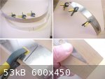
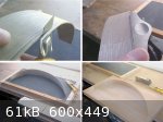
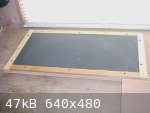
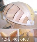
The completed central rib is placed on the mold to check the accuracy of its geometry.
The front end of the rib is held in place with a pin (though a drilled hole to avoid splitting the rib). This hole will eventually be covered by the
bowl end plate.
At the centre section, the rib is held in place using a rubber strap (a strip cut from an old tire inner tube - waste not want not!).
For convenience of working, the mold has been fixed to an adjustable base.
If conditions are favourable tomorrow the central rib will be glued in place so a fresh batch of hide glue has been prepared in anticipation.
|
|
|
jdowning
Oud Junkie
Posts: 3485
Registered: 8-2-2006
Location: Ontario, Canada
Member Is Offline
Mood: No Mood
|
|
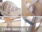
The central rib was glued today. With a week of sunshine in the forecast some progress with the bowl may be possible.
The rib has been fixed in the correct position on the mold using small blocks of pine pinned to the mold bulkheads.
At the neck block the rib has been clamped in place with plastic push pins - after application of hot hide glue. Small card squares underneath the
pins are to prevent damage to the edges of the rib.
At the tail end, the rib has been pinned to the end block of the mold. The end block has been covered with 'oven proof' paper to prevent the ribs
being glued to the mold.
Apart from the rubber band which retains the rib to the mold at the centre - no force is necessary to make the rib conform to the mold profile.
|
|
|
jdowning
Oud Junkie
Posts: 3485
Registered: 8-2-2006
Location: Ontario, Canada
Member Is Offline
Mood: No Mood
|
|
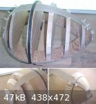
Perfect weather conditions - a shame to spend time indoors - but went ahead with rib #2.
The technique for gluing the ribs is the centuries old method described by Arnault de Zwolle in the mid 15th C - still used by some oud makers like
Dincer Dalkilic working in the Turkish tradition.
Using hot hide glue, the rib joints are held in place with glued strips of paper scorched with a hot iron (to cause the glue on the paper to set
quickly and also to remelt the glue in the joint to obtain a close fit of the ribs). I have never used this method before so this is a 'hands on'
learning process.
The second rib has been prepared so that it will fit against rib #1 and the mold bulkheads without being forced into place.
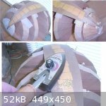
The glued paper strips are freshly made from old, brown paper envelopes - coated with hot hide glue and allowed to dry partially before being cut into
pieces measuring about 25 mm X 20 mm.
The joint surface of rib #2 is first coated with hot hide glue, then - starting at the neck block end - the rib is glued to the neck block. The glue
is remelted with a hot iron and clamped in place with two pins. By this time, of course, the glue applied to the joint surface has 'gelled'. Any
surplus glue on the face of the rib can then be rubbed off to avoid making too much of a mess. The hot iron is then worked over the rib joint -
remelting the glue and closing the joint surfaces. While held in this position, with light side pressure, pieces of glued paper are applied over the
joint and quickly sealed in place with the hot iron. This process is continued until the whole rib joint has been glued.
The paper strips will remain in place until the bowl is complete, released from the mold, and the joints reinforced from the inside with glued
paper.
To prevent the ribs from being glued to the mold, oven heat resistant paper has been placed under each of the bulkheads. However, any ordinary scrap
paper would serve just as well.
The thermostat of the hot iron was set at half of maximum temperature.
The iron need not be a fancy electrical device - a home made iron - a piece of copper with a handle - heated over an electric stove ring or propane
burner would serve just as well - but less convenient.
So far so good!
|
|
|
jdowning
Oud Junkie
Posts: 3485
Registered: 8-2-2006
Location: Ontario, Canada
Member Is Offline
Mood: No Mood
|
|
Steady progress with rib #5 now being fitted. With the current fine weather there is only time to devote to fitting about one rib a day as other work
takes priority.
An advantage of the glued paper/hide glue method of assembling a bowl is that the paper strips, when scorched in place, immediately hold everything
securely together allowing work to proceed on the next rib. No need then to first wait for glue to dry - as would be the case if modern synthetic
adhesives are used. It would be quite possible for an experienced luthier - working to a tight schedule - to assemble a complete bowl, using this
method, in a day or two.
Still gaining experience with this method.
Several glued paper strips were left over from fitting ribs #2 and #3. As the glue on the paper dries and hardens it shrinks causing each paper piece
to curl up. Rather than throw these away, a test was tried on rib #4. By quickly dipping each of the strips in water prior to use the paper strips
flattened out as the paper absorbed the moisture. However, the moistened paper also loses its strength so it was found to be more difficult to 'iron'
the strips over the rib joint - the paper tending to stick to the iron and tear before the glue dried out.
So, the best approach is to freshly prepare the glued paper at the start of each rib gluing operation - this way the paper strips remain flat and
retain their full strength when being ironed into place.
|
|
|
Ararat66
Oud Junkie
Posts: 1025
Registered: 11-14-2005
Location: Portsmouth, UK
Member Is Offline
Mood: mellow yellow
|
|
I love the bridge John - and your photographic documentation including wood shavings mean we never forget the true meaning of the word 'Oud'.
Leon
|
|
|
jdowning
Oud Junkie
Posts: 3485
Registered: 8-2-2006
Location: Ontario, Canada
Member Is Offline
Mood: No Mood
|
|
Thanks Leon - I have some further slight modifications to make to the bridge - apart from removal of the orange shellac - that will improve
functionality of mounting the strings and will remove excess material to further reduce the weight of the bridge (slightly). But more on that
later.
Another nice day so rib# 5 glued in place and rib #6 being fitted.
In a previous thread last year ("Early Oud Construction Methods?"), I ran some experiments to test if the glued paper procedure resulted in the rib
joints being pulled together as the paper shrank (across the 'grain' of the paper) when scorched in place with a hot iron. The paper strips in these
trials were first soaked in water - after which hot hide glue was applied before each strip was place over the rib joint and scorched to instantly
harden the glue. It was concluded that any shrinkage of the paper during scorching had already taken place by the time the glue had hardened so that
no significant tension was applied to the joint by shrinkage of the paper.
Another trial was undertaken today to test if glue applied directly to paper - without the paper being pre-soaked - resulted in shrinkage of the
scorched paper strips across the rib joint - to shrinkage of the hide glue as it dries.
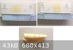
The test simple test rig was made from two strips of spruce - about 10 cm long - freely hinged at one end and with a gap of 0.025 inch (0.63 mm) -
accurately set with an engineers 'feeler' gauge at the other end.
Sample A - the paper was scorched in place with grain direction of the paper parallel to the joint (i.e. the 'curl' direction of the strip is across
the joint). After scorching the joint was found to have closed by about 0.005 inch.
Sample B - with the curl of the paper along the joint - there was no measurable closure of the joint after scorching.
Conclusion to follow.
|
|
|
jdowning
Oud Junkie
Posts: 3485
Registered: 8-2-2006
Location: Ontario, Canada
Member Is Offline
Mood: No Mood
|
|
Conclusions.
As a result of these trials, the procedure to be adopted for gluing the remainder of the ribs will be as follows.
1. Paper strips to be made from relatively strong brown envelope material.
2. Coat paper with hot hide glue - no pre-soaking of the paper - and allow to dry for about 20 minutes or so before use. At this point the paper
strips should be starting to 'curl' slightly as the glue sets - identifying the paper grain direction. Paper strips are to be freshly made for each
rib gluing operation.
3. After cutting to size (about 25 mm square) with scissors, the paper pieces are applied with direction of curl across the rib joint before being
scorched in place with a hot iron to hold the rib joint surfaces in place. This allows any shrinkage of the glue and paper to be used to full
advantage in clamping the rib joint.
The significant shinkage of hot hide glue in drying and its hardness when fully cured (or resistance to yield under stress) is another good reason to
use it for instrument construction.
For those interested, here are a couple of brief, preliminary research papers on the topic recently published in FoMRHI (Fellowship of Makers and
Researchers of Historical Instruments).
The content of these articles is also relevant to the thread "Early Oud Construction Methods?" on this Forum.
|
|
|
patheslip
Oud Junkie
Posts: 160
Registered: 5-24-2008
Location: Welsh Marches
Member Is Offline
Mood: smooth
|
|
great glue articles
|
|
|
jdowning
Oud Junkie
Posts: 3485
Registered: 8-2-2006
Location: Ontario, Canada
Member Is Offline
Mood: No Mood
|
|
Glad that the articles are of interest patheslip.
We have had some very wet weather moving through the area that has raised humidity levels to around 80 % RH so I am delaying the gluing of rib #7 -
now fitted and "ready to go" - until things dry out a bit, hopefully within the next day or two.
In the meantime, the glue test samples A and B have been re-checked and seem to have stabilised with the measured gap for sample A - after glue
shrinkage - reduced from 0.025 inch to about 0.020 inch (and no measurable change for sample B). This equates to a shrinkage of about half that value
for the paper strip - say, about 0.002 inch (0.05 mm) - sufficient to provide a significant clamping force to the rib joint I would think. Certainly,
all of the rib joints so far seem to be closely fitted - although it is difficult to know for sure until the paper strips are eventually removed on
completion of the bowl.
I should mention that - despite the theoretical, symmetrical geometry of each rib - in practice each rib joint must be hand fitted to compensate for
any slight variations in the rib bent profiles, rib thickness or slight inaccuracies of the mold etc.. This results in very small (visually,
imperceptible - I hope!!) rib width variations. So far, I have kept all of the bent rib/ mold variations to less than
1 mm so the final profile of the bowl should be close the original 2mm undersized mold allowance. We will see!
Failure to maintain a tight control throughout the rib fitting procedure can easily cause "ballooning" resulting in the final dimensions of the bowl
being larger (particularly in width) than anticipated.
I like this, centuries old, hide glue/paper strip method over use of modern synthetic adhesives. The 'ancients' knew what they were doing!
Preparation of hide glue is a minor inconvenience compared to modern synthetic, cold set, glues 'out of a bottle' - but the advantages would seem to
far out-weigh these slight disadvantages. No wonder hide glue has held its place, over the centuries, as the superior adhesive for instrument
construction.
|
|
|
| Pages:
1
..
5
6
7
8
9
..
16 |


