| Pages:
1
..
7
8
9
10
11
..
16 |
patheslip
Oud Junkie

Posts: 160
Registered: 5-24-2008
Location: Welsh Marches
Member Is Offline
Mood: smooth
|
|
An elegant solution.
If you follow the line of the tear drop does it intersect the base of the neck?
|
|
|
jdowning
Oud Junkie
Posts: 3485
Registered: 8-2-2006
Location: Ontario, Canada
Member Is Offline
Mood: No Mood
|
|
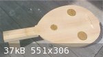
Thanks patheslip. The angle of the tear drop - for this preliminary design - has been determined 'by eye' but referencing the angle to another part of
the oud - tail end of bowl, bridge position, neck joint etc. is a good suggestion worth investigating, just to see how it turns out. This would also
apply if the upper surface of the tear drop is made curved rather than flat. All a bit of guesswork at this stage.
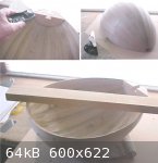
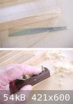
Damp, humid weather but bowl levelling can go ahead regardless. I use a block plane to bring the edge of the bowl quickly to the required level -
frequently placing the bowl, inverted, on my flat MDF work surface to check for high/low spots. To prevent the bowl slipping during this procedure, I
use a cheap, rubber drawer liner, placed on my lap. For final levelling, I use a flat board - with fine grit sandpaper glued to one end - to ensure
that the angle around the edge of the bowl is perfectly correct.
Due to the slight rotation of the end block, previously reported, the bowl will be levelled to about 3 mm higher than design at the tail end of the
bowl.
According to Robert Lundberg "Historical Lute Construction" - some surviving lute bowls of the 16th/17th C were not levelled perfectly flat but seem
to have been slightly 'scooped out' below the sound hole position (providing tension to the soundboard in this area perhaps?). However, there is some
question as to whether this observed 'dip' in the sound board might have been due to later repairs and consequent bowl distortions over the
centuries.
Interestingly, Richard Hankey (DR Oud) in his book "The Oud - Construction and Repair" also observes this feature in the surviving Syrian, Nahat ouds
of the early 20th C.
At this point, I am not sure if I will leave the bowl edge perfectly flat or slightly 'scooped'.
|
|
|
jdowning
Oud Junkie
Posts: 3485
Registered: 8-2-2006
Location: Ontario, Canada
Member Is Offline
Mood: No Mood
|
|
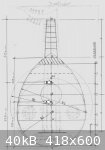
While still speculating about early oud pegbox geometry, I looked at the pegbox geometry of an old (early 20th C?) Egyptian oud, having the now
conventional, modern 'S' shaped profile - just for comparison.
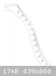
The attached image is a full size tracing of the peg box profile of the Egyptian oud. It may not be typical of oud pegbox design of the period but
demonstrates a potential weakness in the design geometry.
For convenience, I have numbered the pegs in sequence from nut to tail.
It can be seen that with this configuration, all strings lower than peg #4 'ride' either on this peg or peg #5. This is a situation that may affect
the accurate tuning of strings attached to pegs #5 to #12.
However, by adjustment to the upper and lower curvature of radius of the pegbox it is possible to arrive at a geometry where the strings do not
(quite) come into contact with adjacent pegs and where all strings are contained within the peg box profile. Perhaps this might explain why the modern
style peg boxes are 'S' shaped?
So, perhaps, all early oud 'sickle' profile peg boxes must have looked like example 'C' previously posted (or more extreme even with greater radius of
curvature implied by the early Persian miniatures?). If so, this would have made access to the peg box (for string changes) more of a challenge (but
not impossible).
More to think about!
|
|
|
Ararat66
Oud Junkie
Posts: 1025
Registered: 11-14-2005
Location: Portsmouth, UK
Member Is Offline
Mood: mellow yellow
|
|
Hi JD
My Tasos oud has a bowl whose edge is 'scooped' out, ie the curve in the sound board is not simply due to the strings pulling the bridge forward but
extends right to the edges of the sound board.
Whether and how this effects the sound I don't know (logic would tell me it would as it would effect the direction of the many waves and ripples that
a fixed bridge soundboard creates when the strings are activated) ... but it does sound pretty amazing !!
Great thread

Leon
|
|
|
jdowning
Oud Junkie
Posts: 3485
Registered: 8-2-2006
Location: Ontario, Canada
Member Is Offline
Mood: No Mood
|
|
Thanks for your input Leon. I think that I will try 'scooping' the edge of the bowl as an experiment. Of course, I will never know if this improves or
degrades the response compared to a perfectly flat sound board based on this one instrument.
Lundberg observes that for surviving lutes, the amount of the dip from a level surface at the edge of the bowl is no more than 3 mm. He reckons that
this slight dip stiffens and stabilises the sound board. So worth a try!
|
|
|
jdowning
Oud Junkie
Posts: 3485
Registered: 8-2-2006
Location: Ontario, Canada
Member Is Offline
Mood: No Mood
|
|
The bowl is now levelled and the neck is planed down to match. Some adjustment to this 'level playing field' - 'scooping' the bowl edge and neck 'set
back' etc. - will be made later from this datum.
Neck centre line alignment has been determined using a 'centre-finder' ruler taped across the maximum width of the bowl and a straight edge.
The next stage will be to trim and fit the sound board. This will - in turn - determine the final bridge position and neck length.
A preliminary check of dimensions indicates that the string length will be just over 56 cm.
|
|
|
jdowning
Oud Junkie
Posts: 3485
Registered: 8-2-2006
Location: Ontario, Canada
Member Is Offline
Mood: No Mood
|
|
Although hot , humid conditions prevent any component assembly, there is plenty of other work that can continue.
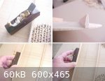
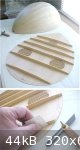
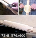
The sound board braces have been shaped to a preliminary 'wedge' shaped section - replicating the brace geometry on my old Egyptian oud. All braces
are of equal height (15 mm), thickness (4 mm) and taper, at the ends, over a distance of about 60 mm to a depth of about 9 mm at the edge of the bowl.
To shape the brace sections, I used the very nice little rosewood plane available from Lee Valley ( Cat#07P15.01) for under $20 Can. (prices have
recently been increased so am not sure of the current cost. I paid $16.95 Can.). This inexpensive, well made, tool is perfect for the job - the sole
is just the right width for planing braces of 15 mm depth - the wooden body does not scar the surface of the sound board (as a metal plane would) and
the plane may be used by either 'pushing' or 'pulling' - dependent upon grain direction.
When planing over the sound holes, the bracing of the rosettes was protected from potential damage with a strip of
1 mm thick wood. A strip of thick card would do just as well.
To taper the ends of the braces, a metal template was made of the required profile and traced onto the rib with a pencil. The little block plane was
then used to trim each brace end to the pencil line. The plane cuts quickly and smoothly without risk of grain 'tear out'.
|
|
|
jdowning
Oud Junkie
Posts: 3485
Registered: 8-2-2006
Location: Ontario, Canada
Member Is Offline
Mood: No Mood
|
|
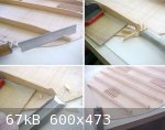
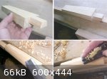
With preliminary planing and shaping of the braces completed, the ends of the braces must be trimmed in preparation for fitting the sound board to
bowl. At this point the sound board is about
12 mm oversize.
The bowl was inverted over the braces, aligned and the brace positions marked in pencil on the side of the bowl. The angle of each brace end was
determined (approximately) using a small bevel gauge. This angle was transferred to a piece of stiff card and the angle marked on the end of the brace
in pencil using the card as a template.
The brace ends will be cut a little oversize to allow for final fitting.
|
|
|
jdowning
Oud Junkie
Posts: 3485
Registered: 8-2-2006
Location: Ontario, Canada
Member Is Offline
Mood: No Mood
|
|
The brace ends are then trimmed using a fine toothed razor saw (smooth cutting across the grain) and the waste then cut and sliced away with sharp
paring chisel.
Final fit is done by shaving and shaping the ends with a sharp knife and file. A close fit to the bowl is necessary to achieve optimum strength of the
sound board to bowl assembly.
The saw used here is another good quality low cost tool from Lee Valley (also available from luthier supply companies). The Lee Valley saw has 53
teeth per inch with 0.010 inch kerf - stiff backed and cuts on the draw, cat# 60F03.10, cost $6.50 Can.
|
|
|
jdowning
Oud Junkie
Posts: 3485
Registered: 8-2-2006
Location: Ontario, Canada
Member Is Offline
Mood: No Mood
|
|
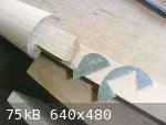
Final fitting of soundboard to bowl.
Two support blocks, 10 mm thick, have been temporarily attached to both ends of the sound board with double-sided adhesive tape. The blocks raise the
edge of the bowl slightly above the braces so that the ends of the braces can be observed and marked to the required length and correct angle (the
angle of the outside ribs - and hence the brace ends - vary along their length - just to complicate things!)
The sound board is placed upon a flat working surface, and, with everything in correct alignment, the bowl is temporarily attached to the support
blocks (using 'masking' tape) and the brace ends marked in pencil ready for trimming.

|
|
|
jdowning
Oud Junkie
Posts: 3485
Registered: 8-2-2006
Location: Ontario, Canada
Member Is Offline
Mood: No Mood
|
|
The final fitting of the sound board to bowl is an important and exacting process requiring careful, step by step trimming/fitting of the end of each
brace - a process of trial and error - not to be rushed.
The tools used to trim the brace ends must be razor sharp and carefully controlled to avoid damage to the sound board surface. A good, low cost, tool
for the job is a commercial, single edged razor blade (cost about $10 for a hundred!). The sound board surface may be protected against accidental
cuts with a piece of veneer but it is better to tape the blade so that only a small section does the cutting (safer to handle as well). The blade is
held in both hands - for precise control - and used with a slicing cut - removing small amounts at a time.
The amount of material to be removed from each brace is a matter of judgment - sight, sound and feel all playing a part - until the bowl fits the face
of the sound board - with everything in perfect alignment and without any forcing - and all bar ends are felt to be in firm contact with the side of
the bowl.
At this stage, the surplus material around the edge of the sound board can be trimmed away - leaving about 3 mm surplus for finishing later. I used a
fret saw and fine jewellers saw blade to trim the waste.
|
|
|
jdowning
Oud Junkie
Posts: 3485
Registered: 8-2-2006
Location: Ontario, Canada
Member Is Offline
Mood: No Mood
|
|
Now that the sound board has been fitted, it is possible to determine the exact position of the bridge and hence the length of the neck (nut to neck
joint = 1/3 string length, neck joint to bridge = 2/3 string length, according to the original, speculative design geometry). From this geometry, the
string length is 56.1 mm - close enough!
At this stage - due to current high relative humidity levels (70%) - gluing the bridge to sound board will be postponed, but work can now continue in
final trimming and shaping of the neck.
|
|
|
jdowning
Oud Junkie
Posts: 3485
Registered: 8-2-2006
Location: Ontario, Canada
Member Is Offline
Mood: No Mood
|
|
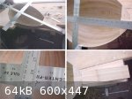
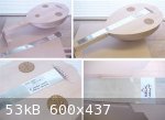
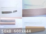
With the sound board fitted, the exact bridge location determined and the neck centre line established - a 'string template' has been made to verify
adequate width of the neck at the neck joint. This template will also be used later to set the bridge alignment prior to gluing.
The template represents the outside area covered by five double courses of strings - measured to the outside of the strings at the nut and bridge -
with a string length of 56.1 cm. The string spacing at the nut is the spacing that I use for my lutes (33 mm overall). The spacing at the bridge is
also one that I use for my lutes which happens to coincide exactly to the string spacing of my old Egyptian oud (65 mm).
The template has been made from thin tinplate (because I have the facilities to accurately cut this material) but I could just as easily have made the
template from thick cardboard cut with a sharp knife and metal straight edge.
Checking the neck layout with the template confirms that there will be about a 3.5 mm space - measured from the outside edges of the treble and bass
strings, to the edge of the fingerboard - at the neck joint. This should be satisfactory.
The next step will be to trim the neck to the required profile and cross section.
|
|
|
jdowning
Oud Junkie
Posts: 3485
Registered: 8-2-2006
Location: Ontario, Canada
Member Is Offline
Mood: No Mood
|
|
The neck blank has been planed back to allow adjustment to string 'action' at a later date. This has eliminated the extra wedge of material added to
the top surface of the the neck blank (as a precaution). The fingerboard will, therefore, taper from about 1.5 mm at the neck joint to about 3 mm at
the nut.
Having established the neck centre line and profile, the neck blank has been cut to the plan and elevation profile on a band saw.
As the neck blank is now tapered in plan and elevation, it must be temporarily mounted (with wood screws) to a pine block so that it may be securely
held in a vice in order to shape the required cross section - which will be semicircular like the bowl section.
Rough shaping is done with a paring chisel and fine shaping with a block plane. Final finishing work will be done with a file.
The neck is made from Sitka Spruce , so will be veneered with harder Ash wood (but also to be consistent with the wood of the bowl - a cosmetic
consideration).The section of the neck must, therefore, be shaped about 1.5 mm undersized. As a guide, metal templates of the required section at the
neck joint and nut were fabricated in order to trace, in pencil, the final neck section.
|
|
|
jdowning
Oud Junkie
Posts: 3485
Registered: 8-2-2006
Location: Ontario, Canada
Member Is Offline
Mood: No Mood
|
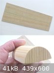
|
Now that the peg box geometry has been defined, a template of the sides has been made in thin metal.
The sides will be a laminate of core material with a veneer of Ash wood.
The Ash wood veneer is just for appearances - to match the the rest of the oud. A piece of Ash wood with curved grain - approximately matching the
curve of the pegbox sides - has been cut into veneer about 2-3 mm thick for this application.
For the inside core of the peg box, two alternatives are under consideration. Beech and Elm wood.
Recent research by ALAMI has indicated that Hackberry - a wood very close to Elm in its cell structure - may have been a candidate for a wood used in
early ouds (See 'Wood Fit for a King' on the Oud Maintenance forum) - although Elm wood (according to Farmer's translation) - may now be a less
certain possibility.
On the other hand, there seems to be no disagreement about Beech wood being a wood that was used for early ouds. Beech is the wood used on my old
Egyptian oud for the inside core.
I have lots of air dried Elm wood to choose from (about 20 years air dried) and some European Beech (only just sufficient for the job - reclaimed from
old furniture, about 50 years old).
Both woods would be suitable for the job. Elm is very tough and difficult to split, similar to Ash in outward appearance. Beech is a darker wood but,
perhaps, more stable than Elm. Elm is lighter in weight (less dense) than Ash or Beech. However, I do not know if there is any evidence for Elm being
used in surviving ouds or lutes.
Decisions decisions! So I may make up laminates of both woods to judge appearance etc. before making a final choice.
|
|
|
ALAMI
Oud Junkie
Posts: 643
Registered: 12-14-2006
Location: Beirut
Member Is Offline
Mood: No Mood
|
|
John, great stuff,
Regarding the neck core. I heard from an old oud maker that the wood chosen for the neck core depends on the size and weight of the bowl "to keep the
balance", I know that the Nahats used spruce for the core, so may be weight is a factor of choice, but I have no clue on what he meant by "Balance",
is there any defined region to keep the center of weight in, by using heavier or lighter wood for the neck core ?
Thought may be it would mean something to you.
|
|
|
jdowning
Oud Junkie
Posts: 3485
Registered: 8-2-2006
Location: Ontario, Canada
Member Is Offline
Mood: No Mood
|
|
Thanks ALAMI - a good question that I have not given thought to before - except for double peg box, extended neck lutes, where balance of the
instrument may be noticeably affected if heavy woods are used for the neck.
I try to build lutes as lightly as possible consistent with strength.
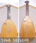
Curious about where the centre of gravity of this oud may be, I ran some tests this morning to find out. The oud is, of course, not complete but could
be assembled sufficiently to assess the balance point - the pegbox with pegs having an estimated weight of 67 grams and fingerboard an estimated
weight of 26 grams. The other unfinished components were weighed on a digital scale (plus or minus 1 gram accuracy). The bowl, soundboard and bridge
assembly weigh 434 grams, neck 88 grams - total weight at this stage of 615 grams.
The temporarily assembled oud (with weights representing the pegbox and fingerboard taped in their appropriate locations) was balanced upon a
cardboard tube clamped to my bench (to prevent it rolling).
The balance point (centre of gravity or C.G.) was found to be a few millimeters above bar #5. Interestingly, this is almost at the mid point of the
overall length of the oud (Point B) measured from the top of the nut to the bottom of the bowl (315:325 mm). Furthermore, using the same procedure to
find the balance point of just the bowl with sound board and bridge in place, the C.G. (Point A) was found to be exactly at the mid point of the
length of the bowl measured from the neck joint to the bottom of the bowl. This rather surprising result (I would have expected the balance point to
be located lower down towards the bridge) was verified by calculating moments of the individual component weights about the measured C.G. of the
assembled oud.
I then used the same procedure to find the C.G. of two of my lutes - both fully complete with strings and tied on frets. As the lutes have
proportionally longer necks than the oud, the C.G. was found to be located closer towards the neck block. In each case, the C.G. position was mid way
between the brace (located immediately above the upper edge of the sound hole), and the inside edge of the neck block. Surprisingly, again the
location of the C.G. was found to be exactly at the mid point of the overall length (top of nut to bottom of bowl) of the smaller lute (34.5:35.5 mm)
and very close to mid length for the larger lute (39.5:40.5 mm).
The small lute is based upon a late 16th C lute by Giovanni Hieber and weighs 647 grams and the large lute - a reconstruction of an early 16th C lute
by Laux Maler - weighs 726 grams.
So, for these three instruments with quite different dimensions, the balance point happens to be very close to the mid point of overall length. These
results may have some significance or may be just coincidental.
I checked out my old Egyptian oud that has a relatively large, thick and heavy bowl, weighing 919 grams assembled (without strings). It has a softwood
neck core. The balance point was found to be at 39:33 mm of the overall length - i.e. positioned more towards the bridge than on the above
instruments.
I understand that Nahat ouds - although they have smoothly rounded bowls externally are then (unlike my Egyptian oud) scraped down inside the bowl to
a uniform bowl thickness of about 1.5 mm. The balance point on these lighter bowl instruments might, therefore, again be at the mid point of overall
length?
It would be interesting to know where the balance point of other surviving old ouds might lie. Any offers?
|
|
|
jdowning
Oud Junkie
Posts: 3485
Registered: 8-2-2006
Location: Ontario, Canada
Member Is Offline
Mood: No Mood
|
|
The neck core has been worked down to about 1.5 mm undersized with a block plane and then finished smooth, and straight with 120 grit garnet paper. I
generally avoid use of sand paper where possible (dust as well as grit on work surfaces that can damage tool cutting edges) but this is a good
application - the wide surface of the paper removing all slight dips and irregularities in the surface left by the plane. I check for surface
irregularities by 'feel' - fingertips can be sensitive enough to detect the slightest irregularity otherwise not visible.
|
|
|
jdowning
Oud Junkie
Posts: 3485
Registered: 8-2-2006
Location: Ontario, Canada
Member Is Offline
Mood: No Mood
|
|
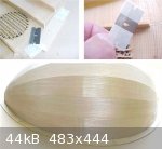
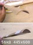
The neck will be veneered with Ash wood cut (with a band saw) from the same rib stock as the bowl. Veneering may be done with a single piece or
multiple pieces. A single piece veneer will not be used as it will be difficult to find a piece with straight and uniform grain from the stock in
hand. I could veneer the core with eleven strips - as a continuation of the bowl ribs but have decided instead to use a two piece 'book matched'
veneer which may be more of a challenge.
Having made a card template of the veneer panel (measured from the finished core) the chosen veneer stock has been planed to just under 2mm thick and
cut oversize to the template. The veneer stock chosen has a grain direction matching the taper of the template as well as some 'pin' knots that should
add some visual interest to the otherwise plain character of the Ash wood. All cosmetic - mainly for appearance.
The curvature of the neck section is quite small (about 40 mm in diameter at the nut end) so the relatively thick veneer will be 'marinated' prior to
bending to soften the wood and allow the veneer to readily conform to the tight curvature of the neck. This is something of an experiment. If it
fails, then I will veneer the neck with strips as an alternative.

|
|
|
jdowning
Oud Junkie
Posts: 3485
Registered: 8-2-2006
Location: Ontario, Canada
Member Is Offline
Mood: No Mood
|
|
The marinade to be used (based upon recent experiments reported in the thread 'Marinated Wood' on this forum) will be 50% Ammonia solution/50% Wood
Alcohol. Two samples of neck veneer have been cut, one about 1.9 mm thick the other about 2. 2 mm thick (to allow for any shrinkage (in thickness) of
the samples due to the effect of the marinating fluid). The thinner sample will be soaked for 7 days before being boiled in water for 5 minutes after
which it will be tied to the neck and allowed to dry to produce preformed veneers (if the bending is successful) that may then be easily glued to the
neck core.
The thicker veneer will be marinated for 14 days prior to boiling - just to see what happens and to obtain more test data. It will be interesting to
see if this extended soaking period will be sufficient to produce cell compression (as recorded in the 'Marinated Wood' tests for Walnut using Ammonia
solution as the marinade) - and hence result in an increase in Specific Gravity (and hardness) of the veneer. A harder, more dense, veneer would be an
advantage on the back of the neck to help reduce wear and damage - particularly from the tied on frets.
Both veneer samples have been weighed before immersion in the marinade in order to keep track of any changes in the veneer density or Specific
Gravity.
|
|
|
jdowning
Oud Junkie
Posts: 3485
Registered: 8-2-2006
Location: Ontario, Canada
Member Is Offline
Mood: No Mood
|
|
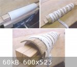
The thinner (1.9 mm) veneers have been marinating in a 50% Ammonia Solution and 50% Methanol (wood alcohol) solution for 7 days in preparation for
pre-bending.
The veneer will be bent on the neck which has been protected with thin card taped in place - centre lines marked as a reference for positioning the
veneer.
The first veneer - after removal from the marinade - was heated on both sides using a hot air gun until all residual fluid was seen to evaporate from
the pores of the wood grain on the surface (about 3 minutes or so). The veneer was then centered on the neck, tied in place with wide 'Hockey Boot'
laces, and left to dry overnight. The wide laces provide a fairly uniform pressure on the veneer to minimise any compression defects on the surface of
the softened wood - particularly at the edges.
On removal from the neck the following day, the veneer had obtained a uniform 'set'. To ensure maintenance of this profile, the veneer was tied with
masking tape and left to dry for a longer period.
The second veneer was subject to the same operation this morning.
The thicker veneer test pieces will be left to marinate for another 7 days - just to see what happens. The detailed results (macro photos of cell
structure etc.) will be posted in a new thread (Marinated Wood Part 2) for information.
|
|
|
jdowning
Oud Junkie
Posts: 3485
Registered: 8-2-2006
Location: Ontario, Canada
Member Is Offline
Mood: No Mood
|
|
Unforeseen circumstances have prevented progress on this project for the past six weeks. As it may be another month or two before I am able to see
well enough to resume fine luthier work, I thought that this enforced interlude might be an opportunity to explore the question of sound holes -
numbers, size, placement etc. - all 'grist to the mill' in this experimental project.
The earliest ouds - to judge from the beautiful Persian miniature paintings of antiquity - had either no sound holes (cut in the sound board) or had
small holes cut around the edge of the sound board. The original purpose of these holes may have been to vent the enclosed space of the bowl to allow
a free movement of the sound board. Of course, ouds represented without sound board 'vents' may have had holes cut in the bowl for the same purpose -
we can never know from the paintings. However, long necked ouds, like the Saz, have a 'sound hole' cut through the end block of the bowl, so it is
quite possible that these early ouds also had this feature.
The venting of the enclosed space of a bowl can be found in other instruments like the modern (Western) orchestral tympani or kettle drum, the
hemispherical copper bowl of the drum having a 'vent' hole in the base - apparently - to equalize pressure in the drum with temperature changes. The
orchestral drums are fine tuned to a desired frequency by careful adjustments to the tension of the drum membrane as well as adjustments to the size
of the vent in the bowl.
More to follow!
|
|
|
jdowning
Oud Junkie
Posts: 3485
Registered: 8-2-2006
Location: Ontario, Canada
Member Is Offline
Mood: No Mood
|
|
Cutting a hole or holes in a soundboard locally removes mass and reduces stiffness which affects the way in which a sound board vibrates and responds.
This effect is likely to be more pronounced for instruments with large open sound holes than for traditional ouds or lutes where the pierced sound
hole rosettes are firmly braced.
A sound hole, however, has another important function in that it allows the instrument to function as a resonator that may be tuned to amplify certain
frequencies of vibration. In this respect, the term 'sound hole' is probably something of a misnomer as it doesn't 'let sound out' from the interior
of the body of an instrument acting only as a resonator vent. It is this well known phenomenon - the so called Helmholtz resonance effect - that I am
interested in exploring as part of this project, just to see where it might lead.
ALAMI recently noted in another thread that classical acoustic guitars have the sound hole sized so that the tone of the 5th String (A pitch) is most
amplified. Having a reasonably resonant classical guitar to hand, it was a simple matter to test this statement by sliding a piece of 3 mm thick card
board over the sound hole while plucking each string individually. Sure enough, the sound volume of the A string suddenly boomed out loudly at the
point when the sound hole was fully uncovered. A similar although less pronounced effect was noticed for the 6th or E string with the sound hole
partially uncovered by about 50%. The effect for the remainder of the strings was judged to be minimal.
So, for a guitar, this design feature is used to improve the bass response.
If this was also found to be the case for ouds and lutes, then it might in part explain the apparently satisfactory performance of gut bass strings in
early plucked instruments. Marin Mersenne, for example, writing in Paris in 1636, notes that the thickest bass strings of a lute (i.e. the 10th
course) had a sustain of 10 to 20 seconds (compare that to modern metal wound nylon basses!).
More to follow
|
|
|
jdowning
Oud Junkie
Posts: 3485
Registered: 8-2-2006
Location: Ontario, Canada
Member Is Offline
Mood: No Mood
|
|
With no in depth experience of musical instrument acoustics it will be necessary to begin at the beginning in this experimental investigation.
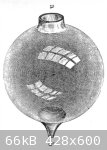
The attached image is an engraving of a 'Helmholtz Resonator' - a device used by the great 19th C scientist Professor Hermann Helmholtz to investigate
the tonal components of sound. The device is a glass sphere with a short neck open to the atmosphere (a) at one end and a small hole (b) at the other
placed in the ear to better hear the resonant frequencies. The resonators are tuned to respond strongly to a specific tone frequency by altering the
volume of the sphere and dimensions of the neck. Helmholtz employed a number of resonators in his experiments - all tuned to different tone
frequencies.
The resonator works when the mass of air in the neck is forced (by the pressure of a sound wave) against the trapped air within the sphere which acts
like a spring causing the air in the neck to oscillate at the tuned frequency.
In Appendix II of his book "On the Sensations of Tone", Helmholtz provides some useful information giving the dimensions of his resonator devices. He
explains that spherical resonators are the most efficient (compared to those of cylindrical, conical or other geometrical shape) - partly because
their other proper tones are very distant from the primary (resonant) tone and so are but little amplified and partly because the spherical shape
gives the most powerful resonance. He goes on to say that "the walls of the sphere must be firm and smooth, to oppose the necessary resistance to the
powerful vibrations of air which take place within them, and to impede the motion of air as little as possible by friction".
He lists the dimensions of 10 of his resonators the ratio of diameter of the neck to diameter of sphere ranging from 0.35 for the smallest sphere to
0.23 for the largest - recommending an optimum ratio of between 0.2 and 0.25 for best results.
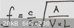
The design of a spherical resonator involves gas thermodynamics, use of differential calculus and all of that good stuff. However, others have done
this work reducing the determination of the resonant frequency to the simple equality given in the attached image where:
f = resonant frequency in Hz or cycles per second
c = the speed of sound in air (343 metres/sec. at 20 C).
A = the cross sectional area of the neck.
V = the volume of the sphere.
L = the equivalent length of the neck
A copy of "On the sensations of Tone" may be downloaded free of charge from
http://www.archive.org
Search "acoustics helmholtz" under "Texts"
|
|
|
jdowning
Oud Junkie
Posts: 3485
Registered: 8-2-2006
Location: Ontario, Canada
Member Is Offline
Mood: No Mood
|
|
It is perhaps obvious that guitars, ouds, lutes, violins etc. are less than prefect 'Helmholtz Resonators' - they have flexible bodies, are not
spherical and are not smooth inside etc. So, does the equation for determining the resonant frequency of a spherical 'Helmholtz Resonator' have any
useful application for designing musical instruments - in particular ouds? I don't know the answer at this point in time.
Before dealing specifically with the oud of this project, my classical guitar might be used to provide some useful data.
A reasonable estimate of the volume of the guitar body was made by tracing the outline of the instrument on to squared paper, counting the squares (to
determine the surface area) and multiplying by the depth of the body - making allowances for the thicknesses of the sides and back, neck block etc.
Calculating the ratio of sound hole radius to the radius of a sphere of equivalent volume gives 0.3 - close enough to Helmholtz's recommended optimum
- so far so good.
However, calculating the resonant frequency using the formula for a spherical resonator gave a frequency of 138 Hz - too high a value - it should have
been around 110 Hz (A440). The difference is around 25% higher than expected - perhaps accounted for by the flexible body of the guitar and higher
interior friction which would result in an over estimate of resonant frequency due to a reduction in the spring effect of the trapped air as well as
the increased frictional resistance.
Note that although the thickness of the sound board at the sound hole is only about 2mm, the 'effective length of the resonator neck' is about 1.7 X
sound hole radius (due to end effects of the column of air in the sound hole). In this case, the effective neck length is about 7.4 cm. Interestingly,
this fact can be roughly verified by placing a hand over the sound hole and tapping the sound board near the sound hole. A distinct pressure pulse can
be felt about 3cm from the surface of the sound board.
|
|
|
| Pages:
1
..
7
8
9
10
11
..
16 |


