jdowning
Oud Junkie

Posts: 3485
Registered: 8-2-2006
Location: Ontario, Canada
Member Is Offline
Mood: No Mood
|
|
Measuring Relative Humidity - D.I.Y.
Very hot, humid environment at present - instrument building (and most other work) at a standstill - so decided to make a simple device to
(indirectly) measure Relative Humidity. The scientific name for the apparatus is an "Aspirated Psychrometer" - simple to make and fairly accurate -
and a 'popular' scientific project, familiar to generations of High School pupils. It took about an hour's work to make.
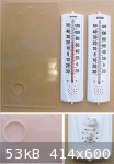
This tool is made from two, low cost 'external' thermometers (the bigger the better - long scale length = better accuracy) available from a local
hardware store.
The bulb and part of the stem of one of the thermometers must be tightly wrapped with a piece of fine muslin or cotton cloth, tied with linen or
cotton thread to hold it in place. This is the 'Wet Bulb Thermometer'. The other - unmodified - thermometer is known as the 'Dry Bulb Thermometer'.
The two thermometers are attached - side by side - with soft copper wire (stripped from household electric wiring) to a plastic sheet back plate (in
this case a piece of scrap Plexiglas or Acrylic). The wire is fed through small holes drilled in the plastic back plate. The back plate, immediately
under the bulb of the "Wet Bulb Thermometer', has been cut out to allow free air flow across the thermometer bulb.
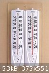
In use, the cloth of the 'Wet Bulb Thermometer' is first soaked with water (that is why it is called 'Wet Bulb') and the unit is then held against a
household electric fan - the faster the airflow the better - until the temperature of the 'Wet Bulb Thermometer' is seen to stabilise at a minimum
value. At this point, both the 'Wet Bulb' and 'Dry Bulb' temperatures are recorded. During this procedure, the cloth of the 'Wet Bulb' thermometer
must not be allowed to dry out.
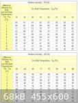
The relative humidity may then be read from the tables attached (either in Centigrade or Fahrenheit units).
No need to understand the exact physics or science behind measuring relative humidity - just that the optimum conditions for instrument building are
found, from experience, to be in the range 45% to 55%.
Instruments that measure Relative Humidity directly - hygrometers - may be purchased at low cost but need to be calibrated to verify their accuracy.
The 'Aspirated Psychrometer' may be used for this purpose - not with laboratory accuracy but good enough for general purposes.
Testing the psychrometer in my workshop I obtained a wet bulb temperature of 20 C and dry bulb 24.5 C giving a difference of 4.5 C. From the charts -
extrapolating - this gave an RH of about 66% (compared to the direct reading of 66% given by my digital hygrometer).
The attached, simplified psychrometric tables (good enough for our purposes) are from http://www.EngineeringToolBox.com
|
|
|
jdowning
Oud Junkie
Posts: 3485
Registered: 8-2-2006
Location: Ontario, Canada
Member Is Offline
Mood: No Mood
|
|
Another simple method that may be used to calibrate a hygrometer is provided by the Canada Mortgage and Housing Corporation.
The hygrometer is placed in an environment of known Relative Humidity for 8 to 12 hours and the scale reading then checked to verify the accuracy of
the instrument.
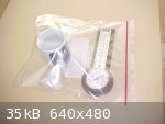
A coffee cup is filled half full with common table salt and a quarter cup of water added and the mixture stirred for several seconds. The cup is then
placed in a sealed 'Ziploc' type freezer bag (5 litre size) together with the hygrometer under test. Do not let the salt water solution come into
contact with the hygrometer! Store in a place away from drafts and sunlight where the temperature is reasonably steady. After 9 to 12 hours note the
reading on the hygrometer scale. It should read 75% RH or close to it. If it does not then either adjust the hygrometer to the correct setting or - if
it is not adjustable - note the error and apply this correction to future readings.
Hygrometers should be calibrated at least once a year.
Testing two low cost hygrometers - one analogue and the other digital - using this method gave a reading of 74% in each case. Close enough.
|
|
|
jdowning
Oud Junkie
Posts: 3485
Registered: 8-2-2006
Location: Ontario, Canada
Member Is Offline
Mood: No Mood
|
|
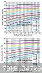
The attached charts from 'engineeringtoolbox' may be more convenient to use than the tables, previously posted, for the psychrometer.
|
|
|
jdowning
Oud Junkie
Posts: 3485
Registered: 8-2-2006
Location: Ontario, Canada
Member Is Offline
Mood: No Mood
|
|
The earliest instruments designed for measuring Relative Humidity (hygrometers) used hair as a 'sensor'. Hair, as an organic material, expands and
contracts along its length - dependent upon the relative amount of water vapour in a volume of air - so, by connecting a length of hair (by means of a
'magnifying' lever mechanism or clock gears) to a dial - the relative humidity can be accurately indicated (after calibration of the hygrometer).
Any organic material that changes dimension with humidity levels may be used as a sensor to construct a hygrometer. What better material than wood
itself?
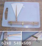
This little experimental project sets out to construct a, simple, low cost hygrometer using wood as a sensor module, but calibrated to indicate the
equilibrium moisture content (EMC) of wood rather than Relative Humidity. The EMC of wood is of primary interest to the luthier when assembling
instrument components in order to maintain optimum conditions. No guarantee that it will work - but here goes!
This hygrometer will be created around a low cost ($1), flat, plastic kitchen cutting board measuring about 27 x 19 cm - as a base board. A plastic
base is best as it is not affected significantly (dimensionally) by humidity fluctuations.

|
|
|
jdowning
Oud Junkie
Posts: 3485
Registered: 8-2-2006
Location: Ontario, Canada
Member Is Offline
Mood: No Mood
|
|
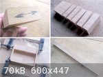
The wooden sensor is made from a small billet of well seasoned Sitka Spruce - slab cut (i.e. with the wood grain running across the section).
Shrinkage/expansion of the wood with humidity change is greatest along the grain.
As the wood billet is only about 50 mm wide (2 inches), it has been sliced into small blocks (on a band saw) and the blocks glued together, end to
end, to make a long piece about 200 mm (8 inches) in length with the grain of the wood running along the length.
This piece has been cut down the centre to make two strips of equal cross section of about 10cm X 10 mm.
|
|
|
jdowning
Oud Junkie
Posts: 3485
Registered: 8-2-2006
Location: Ontario, Canada
Member Is Offline
Mood: No Mood
|
|
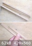
The most basic hygrometer could be made by joining the wood strips together into a longer length and simply measuring the change in length with change
in humidity (the longer length, the greater the expansion/contraction with humidity changes and the greater accuracy).
However, in order to make a more compact hygrometer, the strips forming the sensor have been joined together 'in tandem' with a thin strip of wood
glued to each (and opposite) ends. (the longitudinal expansion/contraction of the connecting strip is very small compared to the expansion/contraction
of the wood strips of the sensor so can be ignored)
The equivalent length of the sensor module - in this case - will be about 350 mm but a greater equivalent length (and accuracy) could be achieved by
joining together multiple modules.
|
|
|
jdowning
Oud Junkie
Posts: 3485
Registered: 8-2-2006
Location: Ontario, Canada
Member Is Offline
Mood: No Mood
|
|
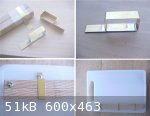
The sensor module should be held in alignment by guides. To simplify the guide arrangement, both sections of the sensor module have been made of equal
length.
The guides are made from thin sheet metal (in this case brass shim but tinplate or aluminium cut from an old can with scissors would do just as well).
Remove any burrs from each strip. To ensure free movement of the sensor module within the guides the sensor is first wrapped with a couple of turns of
masking tape (to create sufficient clearance in the guides).
The strip of metal for each guide is then formed by simply wrapping it around the module. After removal from the module, each guide is then soft
soldered together (or glued with epoxy cement).
The guides are attached to the plastic base board with screws. The plastic is quite soft so - after drilling pilot holes - the screws can be easily
and firmly screwed into the plastic.
After attaching the guides and checking that the sensor module will move freely through the guides, the module is anchored to the base board at the
bottom end. The anchor screw is left a little free and not tightly screwed in place.
|
|
|
jdowning
Oud Junkie
Posts: 3485
Registered: 8-2-2006
Location: Ontario, Canada
Member Is Offline
Mood: No Mood
|
|
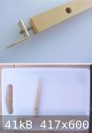
The second component of the hygrometer is the indicator. This has been made from a piece of close grained hardwood (in this case boxwood - but maple
would do just as well).
The end of the indicator has been drilled to accept a 1'' finishing nail - hammered into place and then trimmed to length (about
5 mm). A small metal bracket - that will be glued to the second element of the sensor with epoxy cement - has been drilled oversize to allow adequate
movement of the indicator without 'binding.
This geometry will 'magnify' movement of the sensor by 4X.
Now, all that remains is to attach a scale and calibrate the the unit.
|
|
|
jdowning
Oud Junkie
Posts: 3485
Registered: 8-2-2006
Location: Ontario, Canada
Member Is Offline
Mood: No Mood
|
|
The indicator bracket has been glued to sensor module and final assembly of the hygrometer is complete. The central guide of the sensor has been
removed as unnecessary as well as allowing greater freedom of movement of the sensor components.
A temporary Relative Humidity scale has been calculated and drawn on card. This scale will be checked and verified against readings of a calibrated
digital hygrometer, over the next few months, as environmental conditions change.
The sensor has been custom made from Sitka Spruce soundboard material that I have in stock - so is specifically representative of that batch of wood.
It will be interesting, therefore, to observe how this material expands and contracts with humidity changes - particularly as the wood has been aging
for over 30 years. Does the aging process make wood less sensitive to environmental change as is often claimed? We may now find out (if the hygrometer
works as designed).
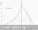
The scale has been calculated using data for Sitka Spruce in the 'Handbook of Wood' published by the U.S. Department of Agriculture Forest Products
Laboratory.
The attached image is a composite of two graphs - one showing the variation of EMC (Equilibrium Moisture Content) with Relative Humidity and the
other the variation of shrinkage as a percentage of the length of the wood when 'green (Fibre Saturation Point - FSP - about 30% EMC) along tangential
grain compared with EMC.
The sensor has been made from Sitka Spruce with the tangential grain oriented along the length of the sensor. The equivalent length of the sensor is
330 mm, therefore, from the graphs, the change of length of the sensor with relative humidity can be determined.
So, for example, the shrinkage at 50% RH is 5.15% and at 65% RH is 4.5% so that the relative shrinkage between these two datum points is 0.65%. This
means that the change in length of the sensor module will be 2.15 mm.
As the magnifying factor of the indicator has been measured as X4.55 - this translates into a movement of the tip of the indicator of 9.8 mm.
Repeating this calculation for values of RH of 30%, 65%, 75%, 85% and 95% from a 50% RH reference enabled the temporary scale to be laid out.
Now to see if it will all work as intended!

|
|
|
DaveH
Oud Junkie
Posts: 526
Registered: 12-23-2005
Location: Birmingham, UK
Member Is Offline
Mood: No Mood
|
|
I like this! It's very nifty and I'll be interested to see how it performs. Now all you need to do is add a clockwork windlass and a roll of graph
paper and a plotter pen to track changes over time!
|
|
|
jdowning
Oud Junkie
Posts: 3485
Registered: 8-2-2006
Location: Ontario, Canada
Member Is Offline
Mood: No Mood
|
|
Hmm - as I recall we had one of those clockwork powered things way back in High School Geography class. I should have paid more attention to it at the
time!
I should add that the EMC/RH graph previously posted has been plotted for values at 70 F (21 C). The values do change with ambient temperature but not
enough to make any significant difference - 70 F being a good average value for most workshop environments. The 'Wood Handbook' gives a full range of
values for temperatures ranging from 30 F to 210 F in 10 F increments (-1 C to 99 C) - see table 3-4.
Also, as relative humidity in my workshop has been hovering around 65% for the past week or two, the scale has been positioned to give a reading of
65% as a starting point.
If the hygrometer works and can be accurately calibrated then the scale can be easily modified to directly indicate EMC as well as RH.
The other unknown about this device is how quickly it will respond to changes in relative humidity. The sensor has been made with a small cross
section and, with end grain surfaces exposed back and front, should respond reasonably quickly but with some time delay (a few hours?) which would
'iron out' any short term fluctuations in RH. This would have the advantage of better representing changes in the moisture content of the sound board
wood of a musical instrument which must also have a similar delayed response to moisture absorption.
For information, I will report on the success (or failure) of the device at a later date.
|
|
|
jdowning
Oud Junkie
Posts: 3485
Registered: 8-2-2006
Location: Ontario, Canada
Member Is Offline
Mood: No Mood
|
|
In order to quickly check the response and mechanical operation of the hygrometer, it was sealed in a plastic 'Ziploc' bag together with a cloth
moistened with water in order to raise the relative humidity inside the bag to maximum.
After 12 hours the sensor was found to be 'bowed' along its length as well as slightly twisted. The wooden spacer connecting the two parts of the
sensor was also bowed along its length. The distortion caused the sensor components to 'stick' in the brass guides.
This fault has been caused by grain 'run out' in the Spruce sensor rods. I did not anticipate that the run out would have caused problems but I should
known better. Both sensor rods must expand and contract in a straight line for accuracy of measurement.
So - nothing for it but to make a replacement sensor - this time with the grain running as straight as possible along the length of the sensor rods.
Also the connecting spacer will be made from thin 'Plexiglass' for dimensional stability with changes in humidity levels. Moisture resistant epoxy
cement will be used throughout for the assembly.
|
|
|
patheslip
Oud Junkie
Posts: 160
Registered: 5-24-2008
Location: Welsh Marches
Member Is Offline
Mood: smooth
|
|
Interesting projects.
To do with your wood hygrometer: I thought that as wood expands more across the grain you'd make it using billets cut this way joined to magnify any
effect.
Probably I'm just confused.
Being sadly pedantic: the word for constructing data points between given data is 'interpolation'
Love your posts.
|
|
|
jdowning
Oud Junkie
Posts: 3485
Registered: 8-2-2006
Location: Ontario, Canada
Member Is Offline
Mood: No Mood
|
|
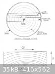
Wood expands/contracts more 'along the grain' with humidity change than it does 'across the grain'.
'Along the grain' means in the direction of the growth rings (tangential) and 'across the grain' means in a direction perpendicular to the growth
rings (radial).
The attached sketches may help clarify matters.
The sensor of the hygrometer is made from slab sawn (tangential grain) wood. Quarter sawn (radial grain) wood could be used but the
expansion/contraction would be much less than that of slab sawn (roughly about half) - with consequent reduced sensitivity of the hygrometer.
For Sitka Spruce radial shrinkage from 'green' to 'oven dry' moisture content is 4.3% whereas tangential shrinkage is 7.5%.
|
|
|
patheslip
Oud Junkie
Posts: 160
Registered: 5-24-2008
Location: Welsh Marches
Member Is Offline
Mood: smooth
|
|
Thanks: I was confused
|
|
|
jdowning
Oud Junkie
Posts: 3485
Registered: 8-2-2006
Location: Ontario, Canada
Member Is Offline
Mood: No Mood
|
|
Not a problem patheslip.
Thanks for asking the question as there are likely to be others who may also be confused about the 'grain direction/ expansion/contraction' matter -
my fault for not explaining things more precisely and clearly.
Pictures are always better than words for getting a message across - particularly in an International, multilingual environment (such as Mike's Oud
Forum)!
|
|
|
jdowning
Oud Junkie
Posts: 3485
Registered: 8-2-2006
Location: Ontario, Canada
Member Is Offline
Mood: No Mood
|
|
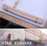
The Mk #2 sensor has now been made and installed. More care has been taken to cut the Spruce so that the transverse grain runs (more or less) along
the length of the sensor rods with minimum 'run out' - three pieces being required to make up the length of each rod.
The rods have been made with a smaller cross section than before so that there is now plenty of clearance in the brass guides. The central guide has
been reinstated (for better control of the thinner rods) and all guides have been 'crimped' on top and sides to reduce the clearances and, at the same
time, providing some flexibility in the guide to ensure a smooth operation of the sensor rods when expanding/contracting with humidity changes.
The connecting spacer between the two sensor rods has been made from a strip of 2 mm thick 'Plexiglass' , Acrylic sheet plastic glued in place at the
end of each sensor rod with epoxy glue.
The completed hygrometer appears to be responding reasonably quickly (within a few hours) to humidity change but further tests must now be made to
verify satisfactory and accurate operation of the unit.
|
|
|


