| Pages:
1
2
3
4
5 |
jdowning
Oud Junkie

Posts: 3485
Registered: 8-2-2006
Location: Ontario, Canada
Member Is Offline
Mood: No Mood
|
|
This humidity level is what we would usually experience here in late August so I guess that there is more yet to come before things eventually settle
down. I am not too concerned about the work that I am currently undertaking where the sub assemblies are free to move without restraint. The
soundboard was finished and braced years ago so at this rate of progress will be eventually glued in place some time during this coming winter - when
humidity levels are 'ideal' - not that I am looking forward to the trials and tribulations of a Canadian winter either. It will be necessary to move
ahead soon with construction of the bowl but that should be less critical with the whole thing being free to expand and contract and 'find its own
level' of stability prior to fitting of the soundboard at the right time.
I am not finding too much of a problem at these humidity levels with 'stifling' of the sound of the lute that I regularly play - it still has a good
resonance. This was not always the case and I attribute this to the passage of time and use of hide glue for soundboard construction. I figure that
under high humidity levels hide glue softens slightly allowing some slight relative movement of components and causing any accumulated residual
stresses to be relieved. Consequently, after many humidity temperature/humidity cycles over the years an optimum low stress level is achieved with
beneficial results acoustically. So in this respect an occasional high level of humidity might be beneficial - so long as it is not maintained for
long periods when things might start to fall apart under string tension. But that is just a theory.
|
|
|
jdowning
Oud Junkie
Posts: 3485
Registered: 8-2-2006
Location: Ontario, Canada
Member Is Offline
Mood: No Mood
|
|
The end block of the lower pegbox/neck extension is now fitted and glued in place. This will be covered completely by the neck joint so I used a plain
piece of sycamore for this part.
To level the assembly and to bring it close to finished thickness, I ran it through a thickness planer - many passes with very fine cuts. Not to be
generally recommended but saved time. This is guaranteed to tear out the grain of heavily figured wood - so plenty of material has been left for final
dimensioning and finishing. The finishing work is done using a scraper plane to eliminate grain tearout. This tool cuts a very fine shaving. The blade
is sharpened like a regular plane blade - with a single bevel - and the edge is then burnished to a slight 'hooked' cutting edge with a burnishing
steel. Here I am using a scraper plane with a fixed blade angle - so the blade has to be sharpened exactly at the correct corresponding angle. A
better design is a plane with adjustable angle. This is one that I bought at a local flea market for $15. I found out why it was so cheap when I
returned home - it has a crack in the side where a previous owner had unsuccessfully tried to remove the pivot spindle with 'brute force'. My eyesight
is not as good as it once was - never mind. The crack has been stabilised with super glue and the plane will eventually be restored with additional
reinforcing brass side plates and a rosewood sole. The handle is made of Brazilian rosewood and the fittings are brass - so still a bargain.
Highly figured wood may also be finished with sandpapers - if all else fails - but I prefer to use cutting rather than abrading tools wherever
possible.
The lower pegbox inside dimension has been made about an inch (2.5 mm) longer than the original as I wanted to provide more room for a slightly wider
peg spacing.
|
|
|
jdowning
Oud Junkie
Posts: 3485
Registered: 8-2-2006
Location: Ontario, Canada
Member Is Offline
Mood: No Mood
|
|
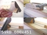
The next stage is to layout and drill the pilot peg holes in the lower pegbox. This is done prior to carving the peg box interior and finishing the
neck extension to size.
A tracing in pencil is first made of the peg box interior onto a piece of card (by laying the pegbox over the card). The centre line is marked, the
peg positions laid out with dividers and the peg centre lines marked at 90 degrees to the peg box centre line. Having counted the peg positions to
ensure that there are, in this case, 13 pegs (it is easy to make a mistake and end up with one peg short - once bitten twice shy! Hence the layout on
card. Card is cheap).
With the correct layout established, the peg centres are transferred in pencil onto both the outside face of the peg box and also the opposite inside
face (by laying the pegbox over the card). The marking of the centres on the inside face is just to provide an additional check of the alignment
during the drilling operation.
Now to make a simple jig to support the peg box at the correct angle for drilling.
A correction - for the record. Referring again to the museum drawing, I note that the original ivory peg heads were not flat sided but have a slight
curve - but not as pronounced as on a violin peg. Nevertheless I shall make the peg heads flat sided - as most pegs of the time period were.
|
|
|
jdowning
Oud Junkie
Posts: 3485
Registered: 8-2-2006
Location: Ontario, Canada
Member Is Offline
Mood: No Mood
|
|
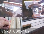
The drilling jig for the lower pegbox will be a simple, quickly made affair - used once and then sent to the scrap box for recycling. Looking through
my box of useful bits, I found this jig that I could re-use and save some time. I have no idea what I used it for previously (always write on a jig to
identify it , just in case it might be needed again in future).
A suitable piece of pine (from the scrap box) was screwed to the upright block (using recycled screws!) and checked for 'squareness' against the
base.
The layout card of the lower pegbox was pinned to this 'back plate' and the marked centre line on the card made parallel with the base using dividers.
The pegbox extension assembly was then correctly positioned over the card and a strip of pine - to act as a supporting surface - was positioned under
the peg box and firmly screwed in place.
Now to drill the pilot holes for the pegs.
It should be noted that it is not absolutely essential to make a jig for drilling the pegholes - it can be done, freehand by eye - but this is best
done with two persons, one observer to check alignment of the drill and one to drill.
If done single handed, a jig is the best way to go - especially if your eyesight is not what it used to be!

|
|
|
jdowning
Oud Junkie
Posts: 3485
Registered: 8-2-2006
Location: Ontario, Canada
Member Is Offline
Mood: No Mood
|
|
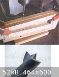
With the jig set up on a drill press and checked for squareness against the drill bit, a couple of holes were drilled to verify alignment. These were
within the level of tolerance, so will go ahead and drill the rest.
I am using an undersized drill bit for the pilot holes so these will be increased in diameter later - this time freehand - using standard drill bits.
A wood boring bit with centre point - 3/16th inch diameter - is being used to cut the pilot holes. This type of bit does not cut as cleanly as a
similar bit with side 'spurs' to scribe the hole diameter but works well enough using a slow 'feed'. A small block of pine is used to temporarily
support the inside face of the pegbox to minimise any damage as the drill 'breaks through'.
|
|
|
jdowning
Oud Junkie
Posts: 3485
Registered: 8-2-2006
Location: Ontario, Canada
Member Is Offline
Mood: No Mood
|
|
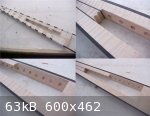
The lower pegbox/neck extension has been finished to the required depth of 16mm and the sides trimmed in the bandsaw to within about 1mm of the
finished dimension. The depth of the peg box is quite shallow on the original instrument - presumably to keep the weight of this component to a
minimum and so provide a better balance to the finished lute.
A cut out in the inside of the pegbox provides clearance for the treble strings. This cut out is easier to make before the back plate is fitted (an
advantage of the built up construction rather than being carved from the solid as the original was). Before shaping the cut out, all of the peg holes
have been reamed undersized. This preliminary operation has been carried out at this stage as maintaining the reamer alignment would be a bit more
difficult if undertaken after the cut out had been completed. The peg hole reaming will be finished, and pegs fitted after the back plate has been
glued in place. There is plenty of material yet to be removed with the peg reamer.
Before reaming the peg holes, the large diameter of the tapered hole is marked in pencil. This is to ensure that no mistakes are made. As a right
handed player I would be less than pleased if I cut a left handed pegbox in error at this stage!
Having previously drilled the pilot holes, each hole has been increased in diameter using ordinary drill bits, like reamers, in a hand cranked drill.
Slow but ensures that control is maintained. This operation reduces the amount of excess material that the reamer must remove and so speeds things up
a bit. Be sure to double check that the correct diameter of drill is being used as work proceeds - oversized holes at either end are not an option!
|
|
|
jdowning
Oud Junkie
Posts: 3485
Registered: 8-2-2006
Location: Ontario, Canada
Member Is Offline
Mood: No Mood
|
|
With humidity levels back up to an uncomfortable 75%, work has been restricted to preliminary shaping operations.
The upper pegbox has been faced at the front with African ebony and brought close to the finished shape by planing and filing. Ebony is hard and
brittle so care has to be taken to avoid chipping the edges.
The slot for the upper pegbox nut has been cut on a router table using a sharp, solid carbide cutter 4.5 mm in diameter and by making several shallow
cuts of increasing depth. For this operation the pegbox was inverted on the router table and traversed by hand against a guide with end stop - a
painstaking task as any slight mistake here could ruin the work. The slot should be a couple of millimeter deeper but it was decided to quit at this
point - while the going was good.
The peg holes have been reamed roughly to size.
It has been decided to fit ebony banding along the edges of the lower pegbox/neck extension - to provide a contrast at the joint between the upper
pegbox and neck extension, to provide a harder edge to the neck extension and also as a decorative feature to complement the inner fillet of the neck
extension. The rebate for the banding was cut on the router table using a solid carbide bit - after running a couple of trials to ensure that the
router would give a clean cut without chipping the highly figured sycamore of the neck extension.
It will be best to glue the banding in place before shaping the interior cutouts of the lower pegbox interior - to avoid the possibility of damage to
the edges of the freshly cut rebates.
|
|
|
SamirCanada
Moderator
Posts: 3404
Registered: 6-4-2004
Member Is Offline
|
|
woah!
nice work!
|
|
|
jdowning
Oud Junkie
Posts: 3485
Registered: 8-2-2006
Location: Ontario, Canada
Member Is Offline
Mood: No Mood
|
|
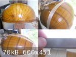
For those interested, here are some images of my router table - home built specifically for my general woodworking requirements. Not a thing of great
beauty - but just as accurate (or more so in some cases) as any commercially available equivalent. It is basically in two parts - a simple wooden
clamped holder for the router that can, in turn, be held in a bench vise, and the table itself made from a piece of 3/8 " (9mm) 'Plexiglass' or
acrylic sheet. This readily available material is stable and perfectly flat - essential for accuracy. The router fits inside a plywood ring screwed to
the table, fitted with wooden 'toggles' to hold it in place. To release the router - if required for freehand use - the toggle clamps are simply
rotated to one side and the router removed.
The router table guide is infinitely adjustable! - just a piece of straight sided pine from my scrap box clamped to the table. The settings of the
guide and router cutter depth are always checked for accuracy by first cutting a piece of scrap wood.
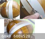
The rebate is cleaned up after routing, to remove any stray 'whiskers', using an "emery board" (here 'borrowed' from my wife's manicure set!) a low
cost tool and perfect for the job.
The banding was cut to size - from an accurately planed strip of ebony - on a bandsaw. I did not take the trouble to change to a fine toothed blade -
a general purpose 4 tpi blade was used - so the banding was cut well oversize to allow for the inevitable chipping of the wood during sawing (ebony is
very hard and brittle). The rough saw cuts will later be removed with a plane.
|
|
|
GeorgeK
Oud Addict
Posts: 46
Registered: 7-16-2008
Location: Canada
Member Is Offline
Mood: No Mood
|
|
Very nice project and thank you for sharing the details.
|
|
|
jdowning
Oud Junkie
Posts: 3485
Registered: 8-2-2006
Location: Ontario, Canada
Member Is Offline
Mood: No Mood
|
|
The banding has been glued in place with a good quality PVA general purpose, woodworking glue (Lee Valley 2002 GF). The rebates were coated with
plenty of glue so that "squeeze out' was visible along the glue lines. The banding was held in place with standard white paper masking tape - pulled
tight by stretching it a little. Stronger stuff is, apparently, available but I have never used it. If a joint is well made and fitted - fairly low
clamping forces are all that is necessary to hold things in place until the glue cures.
The banding has been brought to size by planing with a fine set plane.
The interior pegbox cut outs were made first by removing most of the waste with a sharp woodworking chisel - used with a slicing/paring action to
avoid 'tear out' of the highly figured wood. A small wood rasp then quickly brought everything close to size followed by fine cut files to remove the
coarse marks left by the rasp. Rasps and files (cutting tools) were used to avoid grain tear out.
Everything is now very close to finished size. Humidity levels are still too high so fitting of the back plate and upper pegbox will have to wait.
|
|
|
veyselmaster
Oud Junkie
Posts: 273
Registered: 12-4-2007
Location: turkey
Member Is Offline
Mood: Oud making
|
|
congratulations jdowning 
big project
|
|
|
jdowning
Oud Junkie
Posts: 3485
Registered: 8-2-2006
Location: Ontario, Canada
Member Is Offline
Mood: No Mood
|
|
Thank you for your interest and supportive comments everybody.
This lute is a bit more complicated than others I have previously made - so anything can happen - nothing is guaranteed! However, if I do not manage
to finish the project successfully, it should nevertheless be a learning experience, not only for me but, hopefully, for others who are following this
thread.
Lute or oud, the methods of construction are very similar.
|
|
|
abusin
Oud Junkie
Posts: 442
Registered: 3-23-2006
Location: Manchester England
Member Is Offline
Mood: Ya Fuadi La Tasal
|
|
Hi Mr. jdowning,
I am sure tis will turn out to be a grand oud, judging by your meticulous work and atention to details. I'm sure everyone is following your progress
and indeed it is an educational project to all of us. 
I wish you all the best.
regards,
Awad
|
|
|
jdowning
Oud Junkie
Posts: 3485
Registered: 8-2-2006
Location: Ontario, Canada
Member Is Offline
Mood: No Mood
|
|
Thanks Awad
|
|
|
jdowning
Oud Junkie
Posts: 3485
Registered: 8-2-2006
Location: Ontario, Canada
Member Is Offline
Mood: No Mood
|
|
Still too hot and humid for instrument assembly or anything other than light duty physical work - so spent half an hour planing the strips of yew for
the ribs to remove the rough saw marks - before settling down to recover from these exertions with a refreshing glass of beer! No rush - this
instrument is for my own use.
Nevertheless - "All the time in the world - but not a moment to lose" is a saying always to keep in mind!
The strips were cut from boards years ago when I only had a cheap, inaccurate table saw to do the job - so lots of waste unfortunately - and quite a
rough sawn finish as well.
To save time, each strip was run through my 12-1/2 inch thickness planer - a low cost, light duty machine that does a reasonably accurate job for my
woodworking needs around the home. Planing sections less than 1/4 inch (6mm) in thickness is not recommended on this machine. To get around this
limitation, a 1'' thick pine board - a bit longer than the yew strips - was prepared in the planer. Each strip was then planed by placing it on the
board and running the board and strip together through the planer - taking very light cuts with each pass. This way it was possible to remove all of
the saw marks, make the strips of uniform thickness and reduce the thickness to 2mm. This is the minimum thickness possible with this planer at which
point there is gouging (sniping) over the last couple of inches of each end of the strip - accompanied by an alarming 'crackling' noise - the signal
to quit planing!
With the strips 'rough planed', sections of each strip can now be selected for best match using a thin sheet metal form with the central rib shape cut
out. A form made of card is not as good for this as it tends distort out of shape in use. Once selected, each over sized section will then be hand
planed to the required thickness of about 1.5mm - ready for cutting to shape and forming into the ribs.
At the time that I purchased the yew, I was told that it was "American Yew" but had some doubts due to the width of the boards (about 2 feet wide). I
have since learned that a species of yew native to the Pacific coast of Canada and America (Pacific Yew) typically reaches diameters of 2 ft or more -
the largest tree of its kind growing to 60 ft tall and 6 ft in diameter. So this is likely the species of yew that I have - a specimen tree culled
from the parks of Oxford University. Nice to know the history of the wood that one uses.
|
|
|
jdowning
Oud Junkie
Posts: 3485
Registered: 8-2-2006
Location: Ontario, Canada
Member Is Offline
Mood: No Mood
|
|
Continuing with work that can be done in humid conditions.
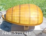
The mold for the bowl has been finished with sealing coats of shellac. The rib layout - as reported earlier in this thread - was marked out using a
flexible metal straight-edge rotating about a fixed point at the neck-block end of the mold and the rib positions carved flat. The neck block - with
the neck joint already cut at the required angle - has been screwed in place. The mold is mounted upon a 3/4 inch (19 mm) plywood base. I prefer this
arrangement so that I can make the outer ribs a little oversize - the raised mold then making trimming of the edge of the bowl easier. More on that
later.
I am not satisfied with the rib layout, as marked out on the mold, which does not seem quite right at the bottom end of the bowl. With this
configuration the ribs on either side of the first, central rib will need to be excessively curved to meet at the end of the mold. The central rib
must, therefore, be made a bit wider at the bottom end of the mold. The rib layout, from the widest point of the mold to the tail block, however,
should be reasonably correct. The geometry of the central rib would seem to be critical but how to determine the optimum geometry? I guess that trial
and error is the only way (for me).
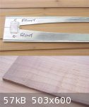
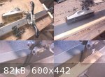
A scrap rib blank of sycamore was reduced to size on a thickness planer and then brought down to 1.5 mm -by hand planing. I used the thickness planer
method, previously mentioned, because the scrap stock was rough cut many years ago and I wanted to save time. However, although it has worked, this is
not a method of thicknessing rib stock that I would recommend. Rib stock - accurately cut on a bandsaw - should be hand planed to finished thickness.
Easier and far less wasteful.
The rib profile - traced from the mold layout - was cut out, well oversize (in the flat) - on a bandsaw. This rib blank was then hot bent to the
required mold curvature until the fit was close without need to force the rib onto the mold surface. The test rib was held on the mold by pins at each
end, pushed into the mold (by the time this project is finished the mold will have as many holes in it as a pin cushion!). In preparation for the next
stage of the operation, pins were also positioned along the length of the rib - on one side - to locate the rib on the mold and prevent any radial
movement.
It is interesting to note the concave curvature of the test rib at this point. This is natural 'fluting' often to be found on lute ribs - the wider
the rib, the greater the concave curvature. Lute ribs are usually around 1mm to 1.5 mm thick, (about half the thickness of oud ribs) - and are left
flat ,not shaped to a semicircular exterior profile like oud ribs.
The fluting of the rib is due to the natural balance of stresses in the rib after bending (known as anti-clastic bending, in engineering terminology)
where the stresses across the rib must balance the stresses induced along the length of the rib. This results in the concave surface observed. The rib
then only contacts the mold along a single line - unless the mold is carved to compensate - which I have not done. However, this will help to ensure
that the ribs do not stick to the mold as work progresses.
|
|
|
jdowning
Oud Junkie
Posts: 3485
Registered: 8-2-2006
Location: Ontario, Canada
Member Is Offline
Mood: No Mood
|
|
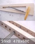
Playing around further with the rib geometry - to find the best fit - the second rib profile was tested. This time a strip of card was pinned into
position on the mold (card is cheap and convenient to use). The profile of the edge of the centre rib was then transferred onto the card using
compasses drawn along the length of the rib joint. The card was then removed from the mold, cut along the pencil line and replaced on the mold with
this edge matching the centre rib. The outer edge of the second rib was then determined by transferring the width of the centre rib to the card at
various points. A smooth curve was drawn through these points to give the profile of the outer edge and the card was cut along this line to give the
complete rib geometry. The card rib was then used to check the next rib position.
After a few trials of this nature I should be able to get a better understanding of how the ribs should lie on the mold for the best overall fit. It
should not be necessary to modify the mold but the ribs when finally fitted will likely not conform exactly to the lines as previously marked on the
mold at the tail end. The lines at the neck block end should be pretty close. I expect that only the centre rib will be symmetrical in profile.
As the ribs are quite narrow in width at the neck block, the plan to use b.w.b. purfling between the rib joints may not be practical due to the
overall width of the purfling. It has been decided, therefore, to use thin lines of African ebony instead. These will be cut from ~1 mm thick planed
stock.
|
|
|
jdowning
Oud Junkie
Posts: 3485
Registered: 8-2-2006
Location: Ontario, Canada
Member Is Offline
Mood: No Mood
|
|
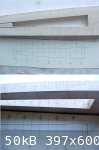
Playing around with card ribs revealed a few small errors in the mold geometry - the centre line was found to be offset by about 4 mm requiring
adjustment of several of the rib 'flats' on the mold. The mold has now been corrected and adjusted by filing and sanding. Absolute perfection is not
the objective because - apart from the first central rib - all of the other ribs will be hand fitted and non symmetrical in profile, due to the
extreme 'flattened' section of the lute. Anyway perfect symmetry is not a feature of surviving lutes made by the master luthiers of the 16th and 17th
C. Well, that's my excuse!
As we now (thankfully - and lets hope that it continues!) have a break in this Summer's unusually wet and oppressive weather conditions and as today
is clear and sunny with relative humidity in the low 60 percent - the corrected mold was taken outside to be given several coats of (fast drying)
shellac to seal the wood grain. The mold will then be waxed and polished to make it as 'glue unfriendly' as possible.
I intend to try building the bowl using hide glue - following the centuries old technique still practiced by master oud luthiers like Dincer - i.e.
glued paper strips scorched and 'ironed' in place with a hot iron to hold the rib joints together as work progresses.
So now I am a bit concerned about the possibility of the ribs being glued to the mold (less likely if a toast-rack or bulkhead mold had been used) but
reckon that the thin lute ribs - that should have a natural concave section after bending - will, therefore, not be in contact with the mold surface
along the length of the rib joints (except at the tail end of the mold which will be protected with a paper overlay). We will see! Nevertheless, I
plan - as an additional precaution - to 'break' any superfluous glue leakage on to the mold with a flexible spatula as each joint is completed.
Allons-y!
|
|
|
jdowning
Oud Junkie
Posts: 3485
Registered: 8-2-2006
Location: Ontario, Canada
Member Is Offline
Mood: No Mood
|
|
Moving on to prepare the African ebony rib fillets.
I am working in unfamiliar territory here as I have always made lute bowls previously without "between-rib" fillets or purfling.
The original lute has parallel sided fillets - rather than tapered fillets - so that is how I plan to proceed.
A strip of ebony veneer was cut on a bandsaw to about 2mm thickness and the saw marks on both sides removed with a plane and finished with a cabinet
scraper. The target thickness of the finished fillets is to be about 0.8 mm. The depth of each fillet will be about 2 mm - to be cut on a band saw.
African ebony is brittle so - in order to minimise chipping of the wood during cutting - the band saw blade was changed to a fine tooth (14 t.p.i.),
metal cutting blade and the standard fairly wide gap between the blade and the table was minimised by running a strip of scrap pine into the blade to
provide, temporary, zero clearance, support during the sawing process. This worked quite well although some slight chipping is inevitable.
Before each depth cut in the bandsaw, the sawn edge of the ebony veneer was smoothed with a plane by "shooting " the edge - that is by running the
plane on its side along the edge to remove all saw marks.
|
|
|
jdowning
Oud Junkie
Posts: 3485
Registered: 8-2-2006
Location: Ontario, Canada
Member Is Offline
Mood: No Mood
|
|
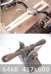
Each fillet strip was then reduced to the required thickness using a simple thicknessing jig - subject of an earlier post in this thread. Each strip
was placed in a slot in the jig, of appropriate depth, a plane was placed over the strip with the blade held at an angle of about 45 degrees, and the
strip repeatedly pulled under the sole of the plane to shave the strip to the required thickness. Note the spiral shavings produced.
The final finish was produced by drawing the strip under a scraper blade held at the correct angle.
|
|
|
Peyman
Oud Junkie
Posts: 496
Registered: 7-22-2005
Member Is Offline
Mood: Mahoor
|
|
Is it possible to use ebonized fillets (like painted maple) for this purpose? Or would they bleed into the next rib? I am curious. It would be easier
to bend maple, it seems.
|
|
|
jdowning
Oud Junkie
Posts: 3485
Registered: 8-2-2006
Location: Ontario, Canada
Member Is Offline
Mood: No Mood
|
|
I expect to encounter some difficulty in bending the ebony fillets due to the brittleness of the wood so shall be running a test on this first batch
of fillets to see how it goes before proceeding further. I plan to pre-bend the fillets together as a bundle.
If I encounter too many problems I may resort to my original plan to use black-white-black purfling between the ribs - or even dispense with using
inter rib fillets/ purfling altogether.
I make my own purfling from maple veneer - natural for the 'white' and dyed black. Dyed veneer may be purchased in a variety of colours. The veneer is
dyed under pressure so penetrates the full depth of the veneer. I have used this purfling as an inlay on instrument soundboards without any problem of
the dye 'bleeding' either into the 'white' veneer or the surrounding spruce wood.
A single thickness of dyed black veneer might be too thin to use alone as a fillet as the surfaces of the veneer should be smoothed before use. Two or
three layers glued together might be a possibility
I have also tested this purfling for hot bending in both lateral and longitudinal directions without problem - it bends easily without breaking. See
the bent samples in my recent thread on this forum "Waste Not Want Not-Yet Another Bending Iron"
|
|
|
jdowning
Oud Junkie
Posts: 3485
Registered: 8-2-2006
Location: Ontario, Canada
Member Is Offline
Mood: No Mood
|
|
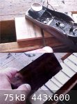
A minor set back. Yesterday, when taking images for posting on the forum, I managed to drop the plane being used to thickness the fillets on to the
concrete floor of my workshop. The result is a broken cast iron, lever style blade tensioning device. Fortunately, that appears to be the only damage
in evidence.
The plane is an old style Stanley 601/2 low angle block plane with an adjustable throat that I purchased new in the 1960's. This plane is not
particularly well made or machined but was made to work with a bit of adjustment and I have since used it quite a lot over the years. It is the only
adjustable throat plane that I have so repairs were undertaken this morning.
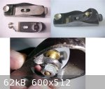
As repair of the broken component is not feasible, the plane has been modified by providing a brass screw in place of the tensioning lever. The
knurled screw is from Lee Valley cat# 00M91.01 with standard 1/4-20 thread that I happened to have in stock.
The old pivot pin on the plane was removed, the casting drilled out to 1/4" diameter and a steel nut was cemented in place under the casting with
epoxy glue. As the nut will always be subject to a compressive load - the epoxy is only required to permanently hold the nut in position so should be
fine for that duty.
With the plane dismantled, the opportunity was taken to lap the sole of the plane flat. This should be done with the blade locked in place (to take
care of any distortion of the casting) so will check this again once the epoxy has set for 24 hours and the plane is ready for use again.
|
|
|
patheslip
Oud Junkie
Posts: 160
Registered: 5-24-2008
Location: Welsh Marches
Member Is Offline
Mood: smooth
|
|
Invaluable
|
|
|
| Pages:
1
2
3
4
5 |


